Quick wins for a faster PC:
Repair Windows errors before they cause bigger problemsFix Now →Fix the driver behind crashes, sound loss and screen glitchesFind Drivers →A Raspberry Pi 2 can serve as the central controller in a home-automation project, while Arduino UNO boards handle room-level sensors and relay outputs. In the documented 2015-era design, the boards communicate over I2C: the Pi sends commands, and each Arduino monitors inputs such as motion, temperature, or light level and switches assigned loads. This is a historical maker architecture, not a current product recommendation; check that the hardware and Windows 10 IoT Core development tools you plan to use are available and suitable before building.
How the Raspberry Pi 2 and room controllers fit together
The Raspberry Pi 2 Model B acts as the hub. In Anurag S. Vasanwala’s 2015 Hackster project, an Arduino UNO in each room is an I2C slave. The Pi communicates with the room boards, and each Arduino reads local sensors and controls relay channels. Giving each room board a distinct I2C address lets the hub distinguish one room controller from another. A separate software identifier such as R1/Dev0 can identify a device within a room; it is an application-level room/device label, not a replacement for the I2C address.
This division keeps sensor connections and relay outputs near the room they serve. It also means the Pi’s software needs a consistent mapping from each room address to its devices and actions. Decide that map before writing event rules so a command for a light cannot be confused with one for a fan or socket.
What parts and software are needed?
- Hub: Raspberry Pi 2 Model B with appropriate power, storage, and enclosure hardware.
- Room controllers: Arduino UNO boards, one per room in Vasanwala’s distributed design.
- Switching hardware: relay channels for the loads, plus the I2C relay or port-expander hardware appropriate to the chosen architecture.
- Sensors: the Vasanwala design uses PIR motion, LM35 temperature, and LDR light sensors. Christian Kratky’s separate 2015 Hackster implementation uses DHT22 temperature/humidity sensors and includes motion and reed inputs.
- Prototyping materials: breadboard, jumper wires, and any interface or protection components required by the selected boards and sensors.
- Development tools: Windows 10 IoT Core, Visual Studio 2015 with UWP tooling, the Arduino IDE, and a PowerShell deployment workflow are the tools described in the project material.
These are parts and tools from legacy project descriptions, not a guarantee of present-day availability, compatibility, or support. Confirm that the exact board revisions, software packages, and deployment path can still be obtained and used in your environment.
Free tools Windows power users keep installed
One-click scans. No signup required.
#1 Best Overall
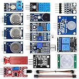
- SMART HOME LEARNING KIT--This kit combines the most common electronic components of smart home projects,developed specially for those beginners who are interested in Arduino and raspberry pi DIY.
- THE PROFESSIONAL SMART HOME KIT--This has 16 sensors modules and delicately selected sensors to detect temperature, humidity, sound, light, infrared, motion, flame,vibration,digital touch, air pressure and many other commonly-used sensors modules.
- THE MOST COMPLETE SMART HOME KIT--This universal kit are compatible for Arduino UNO R3 / Mega2560 / Mega328 /Nano / Raspberry Pi, it could DIY 16 projects according to your need.
- HIGH QUALITY GUARANTEE--We eliminate many old-fashioned sensors which have low reliability and duplicate function as other sensor in the kit, the kookye modules sensor kits are choosed carefully for our user.
- DETAILED TUTORIAL ON OUR WEBSITE--Our website provide step-by-step instruction, detailed circuit connection graph/video, verified sample code and library package which can save lot of user's research time and speed up the learning progress.
Which documented architecture should you follow?
Two projects illustrate different ways to build around the same hub-and-actuator idea. They are examples rather than interchangeable kits: their hardware layouts and software differ.
| Design choice | Vasanwala (2015) | Kratky (2015) |
|---|---|---|
| Room topology | An Arduino UNO in each room acts as an I2C slave. | Uses I2C relay and port-expander boards with the Raspberry Pi 2. |
| Inputs | PIR motion, LM35 temperature, and LDR light sensors. | DHT22 temperature/humidity sensors, with motion and reed inputs described. |
| Interface and telemetry | Local controller design with web and Azure extensions discussed. | Project describes a web app, logging, and Azure integration. |
| Useful distinction | Room-level Arduino boards distribute sensor and relay I/O. | Direct I2C expansion is an alternative to putting an Arduino in every room. |
Kratky describes the repository as containing “the Visual Studio 2015 Solution and all depending projects.” Vasanwala characterizes the project as a basic-to-intermediate way to learn embedded and software-system fundamentals. Those descriptions help set expectations: these are learning projects, and their implementations should not be assumed to provide a finished, safety-certified house-control system.
Rank #2

- Includes Raspberry Pi 5 with 2.4Ghz 64-bit quad-core CPU (8GB RAM)
- Includes 128GB Micro SD Card pre-loaded with 64-bit Raspberry Pi OS, USB MicroSD Card Reader
- CanaKit Turbine Black Case for the Raspberry Pi 5
- CanaKit Low Noise Bearing System Fan
- Mega Heat Sink - Black Anodized
How to build the basic system
- Prepare the hub. Set up the Raspberry Pi 2 with Windows 10 IoT Core and network access using a deployment route that is still available to you. Confirm that you can deploy and run a minimal application before adding hardware.
- Program each room controller. Use the Arduino IDE to configure each UNO as an I2C slave. Assign a unique address to every controller and record which physical room it represents.
- Connect room inputs and outputs. Wire the selected sensors to Arduino inputs and the relay-control interface to the intended relay channels. Check the electrical requirements and signal compatibility of every module; do not assume that similarly named boards have identical interfaces.
- Define the device map. Give each controllable load a stable identifier, such as the documented room/device pattern R1/Dev0. Record which I2C room address and relay channel correspond to each identifier.
- Deploy the controller. Build and deploy the Windows IoT controller or background task from Visual Studio. Start with a simple command and verify that it reaches only the intended room controller and output.
- Add event rules incrementally. Once manual control is reliable, add rules such as turning on a light after a motion event or responding to an LDR light-level threshold. Test sensor readings and switching behavior independently before combining them into automatic rules.
How should lights, fans, and sensors be handled safely?
Relays are the switching interface between low-voltage control electronics and a load; they do not make a circuit safe merely because a Raspberry Pi or Arduino controls them. The project descriptions do not establish relay ratings, enclosure requirements, wiring methods, or compliance for a particular home installation. Select hardware rated for the actual load and installation, isolate and enclose hazardous voltage appropriately, and have fixed mains wiring designed or completed by a qualified electrician. Keep breadboard prototyping on the low-voltage side, and do not route household mains through a breadboard.
For initial tests, use low-voltage indicators or other appropriately safe test loads. Then verify each sensor’s readings and each relay’s intended response independently. Fans and other motor loads should be assessed for their electrical characteristics rather than treated as equivalent to a small light; the available project descriptions do not specify suitable relay ratings for any particular appliance.
What can be extended, and what is not part of the basic build?
The core pattern is hub, addressed I2C controllers or expanders, sensor inputs, and relay outputs. Kratky’s project demonstrates a web interface, logging, and Azure integration as part of a separate implementation. By contrast, timed schedules, RF or infrared links, and mobile or cloud additions should be treated as later extensions unless you implement and verify them separately. The project summaries do not establish a universal maximum number of rooms, a supported cable length, or performance figures, so do not infer those from the use of I2C alone.
Quick Recap
Best Value

- Includes Raspberry Pi 4 4GB Model B with 1.5GHz 64-bit quad-core CPU (4GB RAM)
- Includes Pre-Loaded 32GB EVO+ Micro SD Card (Class 10), USB MicroSD Card Reader
- CanaKit Premium High-Gloss Raspberry Pi 4 Case with Integrated Fan Mount, CanaKit Low Noise Bearing System Fan
- CanaKit 3.5A USB-C Raspberry Pi 4 Power Supply (US Plug) with Noise Filter, Set of Heat Sinks, Display Cable - 6 foot (Supports up to 4K60p)
- CanaKit USB-C PiSwitch (On/Off Power Switch for Raspberry Pi 4)
Rank #4

- Complete Project-Based Learning Path – Build 13 progressive projects (LED blink → button control → PIR motion sensor → music playback → motorized doors/windows → SK6812 RGB lighting → fan control → LCD display → gas alarm → temperature/humidity monitor → RFID door unlock → Morse code access → WiFi control → mobile APP remote control). Each project builds on the previous one, ensuring you understand both the electronics and the programming logic behind every smart home feature.
- Master Two Industry-Standard Languages – Learn to code in both Arduino C++ and MicroPython with 13 detailed tutorials for each language. Compare how the same hardware behaves under different programming approaches – a valuable skill for any aspiring engineer. Perfect for classrooms teaching multiple coding languages or self-learners who want flexibility.
- Build a Real WiFi-Controlled Smart Home – Assemble the wooden house structure and integrate sensors to create a functioning smart home system. Control lights, fans, door servos, and RGB lighting directly from your mobile APP (iOS/Android) . Experience how IoT works in real life – from manual control to automated responses based on temperature, humidity, motion, and gas detection.
- Comprehensive Online Wiki with No Guesswork – Our detailed online tutorials (also accessible via the packaging) include wiring diagrams, full code explanations, and step-by-step assembly guides for every project. Whether you're a complete beginner or a teacher preparing lessons, the structured content eliminates confusion and helps you succeed from project 1.
- Everything You Need to Get Started – (TIPS: Batteries are NOT Included)This kit includes the ESP32 development board, expansion board, wooden house parts, all sensors and modules (DHT11, PIR motion, gas sensor, RFID, SK6812 RGB, servo motors, fan, LCD1602, etc.), and connection cables. NOTE: 6x AA batteries are required (NOT Included). The kit is unassembled – you'll build it yourself following our online tutorials, making the learning experience truly hands-on.
Product prices and availability are accurate as of the date/time indicated and are subject to change. Any price and availability information displayed on Amazon at the time of purchase will apply.