To control an electronic relay, use a low-voltage signal to energize its coil or relay input—never connect a bare relay coil directly to a microcontroller GPIO unless the device documentation explicitly permits it. For most projects, choose one of four approaches: build a transistor or MOSFET driver, use a prebuilt relay module, install a board designed for your Arduino or Raspberry Pi, or use an enclosed isolated controller for mains loads.
Important: exposed mains wiring should not be assembled on a breadboard or handled while energized. Use an appropriately rated enclosure, fuse, strain relief, wiring, and isolation—or have a qualified electrician complete permanent construction wiring.
As an Amazon Associate I earn from qualifying purchases.
How a relay works
A relay separates the control circuit from the switched circuit. A low-voltage signal energizes a coil or electronic input; contacts on the load side then open or close a separate circuit.
- COM (common): the moving contact.
- NO (normally open): disconnected when idle and connected to COM when energized.
- NC (normally closed): connected to COM when idle and disconnected when energized.
Electromechanical relays use a coil and physical contacts. Solid-state relays use semiconductor switching devices and have no moving contacts. The relay’s coil voltage and current describe the control side; the contact rating describes the load side. A relay marked “250 VAC” does not mean that voltage belongs anywhere near a microcontroller.
#1 Best Overall

- 1. Wireless Remote Control Kits - The DC 12 volt relay switch is equipped with 4 channel wireless receiver that built with high stability, security and performance. While the included 2 remote controls transmit strong signal that can pass through walls, floors and doors, steadily control receiver from any place within a reliable distance, max range up to 164ft/50m with no obstacle.
- 2. Home Automation Security Relay - Learning code of 433mhz wireless transmission module has high-level security for its low repetitive rate and re-learn mode, by which it can delete the old code and re-learn a new code when a remote control get lost, so you are always in control of it.
- 3. Remote Relay with 3 Modes of Operation – Use a jumper to configure 3 modes of operating selection pulse / momentary, hold / toggle and latching mode. 4 independent relay channels can either work together (in latching) for polarity reversing or individually (in pulse / hold) to control different electronics, such as two channels for garage door controller motor, the other two for entry lights.
- 4. Easy and Flexible Switch Relay – The wireless relay kit is a perfect remote switch for those hobbyists with home automation DIY projects or business Industrial electrical. The power input voltage is 12V, and each receiver’s relay capacity is up to 20A@14VDC and 20A@125VAC.
- 5. Wide Applications – The wireless remote control switch can be widely used in short and long range turn devices on / off wirelessly, anti-theft alarm control panels, lifts, boats, motor-driven curtain, roller blinds, garage door openers, gate barriers, motorcycles, vehicles, cars, trucks, RVs, electric generator, electric door release locks, windows, manual switches extender, LED lighting lamp bulbs and strips, entrance and access control etc.
When selecting a relay, check coil voltage, coil current or resistance, pick-up and drop-out voltage, contact form, AC and DC ratings, inrush capability, minimum load, electrical life, mechanical life, and creepage and clearance. A rating suitable for a resistive heater may not be suitable for a motor, compressor, lamp, transformer, or switching power supply. See Omron’s relay fundamentals for selection terminology and load considerations.
The circuit rule every method follows
Many GPIO pins cannot safely supply the current required by a relay coil. A coil is also inductive: when its current is interrupted, it produces a voltage spike that can damage the GPIO or switching transistor.
The usual solution is a low-side driver:
Vrelay
  |
 Relay coil
  |
  +----|<|----+
  | flyback    |
  | diode      |
 Drain/collector
 MOSFET/NPN
 Source/emitter
  |
 GND
With an NPN transistor, connect the GPIO through a base resistor, the emitter to ground, and the collector to the coil’s low side. With a logic-level N-channel MOSFET, connect the GPIO to the gate, the source to ground, and the drain to the coil’s low side. A small gate resistor and gate pulldown help control switching and prevent accidental activation during reset.
Crashes, No Sound, or Screen Glitches?
Random freezes, missing sound and display glitches usually trace back to one bad driver. Find and replace yours safely.Free scan · under a minuteWindows Errors? Fix Them Before They Spread
Repair common Windows errors and clear accumulated junk for a smoother, more stable PC - no reinstall needed.Free scan · no reinstallUse a relay supply capable of handling the coil’s pull-in current. Share ground between the controller and driver unless the design is genuinely galvanically isolated. Verify that a 3.3 V GPIO can meet the module’s input requirements; a “5 V relay” is not automatically 3.3 V compatible. TI explains the need for a transistor stage and protection diode in its relay-drive guidance.
1. Build a discrete transistor or MOSFET driver
A discrete driver is the best approach for learning, custom PCBs, unusual coil voltages, multiple relays, or designs that need specific diagnostics and suppression.
Rank #2

- 1. Wireless Remote Control Kits - The DC 12 volt relay switch is equipped with 4 channel wireless receiver that built with high stability, security and performance. While the included 2 remote controls transmit strong signal that can pass through walls, floors and doors, steadily control receiver from any place within a reliable distance, max range up to 164ft/50m with no obstacle.
- 2. Home Automation Security Relay - Learning code of 433mhz wireless transmission module has high-level security for its low repetitive rate and re-learn mode, by which it can delete the old code and re-learn a new code when a remote control get lost, so you are always in control of it.
- 3. Remote Relay with 3 Modes of Operation – Use a jumper to configure 3 modes of operating selection pulse / momentary, hold / toggle and latching mode. 4 independent relay channels can either work together (in latching) for polarity reversing or individually (in pulse / hold) to control different electronics, such as two channels for garage door controller motor, the other two for entry lights.
- 4. Easy and Flexible Switch Relay – The wireless relay kit is a perfect remote switch for those hobbyists with home automation DIY projects or business Industrial electrical. The power input voltage is 12V, and each receiver’s relay capacity is up to 20A@14VDC and 20A@125VAC.
- 5. Wide Applications – The wireless remote control switch can be widely used in short and long range turn devices on / off wirelessly, anti-theft alarm control panels, lifts, boats, motor-driven curtain, roller blinds, garage door openers, gate barriers, motorcycles, vehicles, cars, trucks, RVs, electric generator, electric door release locks, windows, manual switches extender, LED lighting lamp bulbs and strips, entrance and access control etc.
Parts and checks
- Relay with a coil voltage matching the relay supply.
- NPN transistor or logic-level N-channel MOSFET sized for the coil current and voltage.
- Flyback diode for a DC coil.
- Base resistor for an NPN design.
- Optional MOSFET gate resistor and pulldown.
- Power supply with sufficient pull-in-current capacity.
Choose the transistor for coil current, dissipation, switching conditions, and voltage margin. Confirm whether the relay is DC, AC, latching, polarized, or fitted with an internal diode. An AC coil needs a different driver and suppression strategy than the common DC-coil circuit above.
A diode across a DC coil is simple and protects the switch, but it slows the coil’s current decay and can increase release time. A diode-plus-Zener network can release the relay faster while subjecting the transistor and suppression components to higher voltage stress. Omron’s drive guidance covers these trade-offs.
Quick wins for a faster PC:
Repair Windows errors before they cause bigger problemsFix Now →Scan for outdated or missing drivers - takes under a minuteDriver Scan →Clear out junk files and repair common Windows errorsFree Scan →For designs that need controlled peak and holding current, a dedicated device such as TI’s DRV120 relay and solenoid driver can be considered. It is usually unnecessary for a simple one-off project.
2. Use a prebuilt relay module
A relay module normally combines the relay, driver transistor or MOSFET, suppression diode, indicator LED, input circuitry, and screw terminals. Typical connections are:
VCC   Module supply
GND   Ground
IN1   Control input
COM   Common load terminal
NO    Normally open
NC    Normally closed
Modules are convenient, but “relay module” is not a standardized interface. Check all of the following before wiring it:
Rank #3

- 12V Bistable Control Logic** Press once to start, press again to stop – stays locked. Ideal for home appliances, lighting, factory equipment control.
- 2 - Pack Kit + Screwdriver** Comes with 2 relay modules (50×25.5×19mm, 300mm wires) + 1 screwdriver. All - in - one for DIY/industrial setups.
- Reliable Performance Specs** Handles 250V 10A AC / 30V 10A DC (avoid 2000W long - term). Anti - interference & reverse - polarity protection included.
- Easy Installation & Testing** Panel - mountable, pre - wired design. Built - in test button checks stability. Perfect for quick DIY/industrial deployments.
- Wide Compatibility** Works with external switches/sensors (low - level trigger). Suits home automation, industrial control systems.
- 3.3 V or 5 V input compatibility.
- Active-high or active-low triggering.
- Whether the control ground must be shared.
- Whether the coil has a separate supply input.
- Whether an optocoupler provides real isolation or is only an input component.
- Whether contact ratings apply only to resistive loads.
- Whether the PCB traces and terminal block support the advertised current.
Some boards use a jumper to select trigger behavior. Never assume that HIGH means on. Read the documentation or measure the input behavior.
What’s actually slowing this PC down?
Pick the symptom - the matching free tool is one click away.
Arduino-style binary test
const int RELAY_PIN = 7;

void setup() {
  digitalWrite(RELAY_PIN, LOW);   // Reverse for an active-low module
  pinMode(RELAY_PIN, OUTPUT);
}

void loop() {
  digitalWrite(RELAY_PIN, HIGH);  // On for an active-high module
  delay(1000);
  digitalWrite(RELAY_PIN, LOW);   // Off
  delay(1000);
}
Use a digital output for a conventional on/off relay. The pin number, supply voltage, initialization order, and active level are board-specific. High-frequency PWM is not a generic relay-control method; a conventional relay normally needs a stable on or off signal.
3. Use a platform-specific shield, HAT, or add-on board
An Arduino shield, FeatherWing, Raspberry Pi HAT, or similar board simplifies wiring and may provide multiple relays, indicators, mechanical compatibility, and example software. It is a good choice when the project benefits from a compact, repeatable layout.
The trade-off is reduced flexibility. The board may occupy specific GPIO pins, require soldering, conflict with another expansion board, depend on an outdated library, or behave differently during startup and reset. Keep the relay pin in a configuration constant and wrap control in clear functions such as setRelay(true) and setRelay(false).
Raspberry Pi example
This example uses GPIO Zero and BCM GPIO 18. GPIO numbering and library behavior should be confirmed for the particular Raspberry Pi OS installation and board.
Rank #4
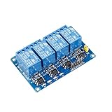
- This is a 4-channel 5V relay interface board, which can control various appliances and other equipment with large current, each need driver current of 15-20mA
- Note: This item is suitable for ages 14 and up
- Product type: RELAY
- Brand: SUNFOUNDER
from gpiozero import OutputDevice
from time import sleep

relay = OutputDevice(18, active_high=True, initial_value=False)

while True:
    relay.on()
    sleep(1)
    relay.off()
    sleep(1)
For an active-low module, use active_high=False. GPIO 18 is only an example, not a requirement. GPIO Zero’s OutputDevice makes relay polarity explicit; the board’s documentation remains authoritative.
4. Use an enclosed, isolated interface for mains
For household AC or other hazardous voltage, use a purpose-built enclosed power-control product instead of exposing mains terminals on a breadboard or open PCB. An enclosure can provide safer terminals, insulation, strain relief, surge protection, and a defined low-voltage control interface, but it does not remove the need for correct installation.
Adafruit lists its IoT Power Relay as an enclosed four-outlet controller with optical isolation, surge protection, and listed control-input options of 3–60 VDC or 12–120 VAC. Product availability and specifications can change, so verify the current product page before purchase.
The older PowerSwitch Tail II is identified by Adafruit as discontinued. Its page is useful as a historical example of the enclosed-relay category, not as a current recommendation.
Do these 3 things before closing this tab:
1Fix the driver behind crashes, sound loss and screen glitches2Clear out junk files and repair common Windows errors3Scan for outdated or missing drivers - takes under a minuteDo not choose a mains relay solely because its label says “10 A” or “15 A.” Confirm whether the rating applies to resistive, motor, lamp, capacitive, or general-purpose loads; account for inrush, temperature, duty cycle, fuse protection, wire gauge, grounding, insulation, terminal ratings, and local electrical codes. Do not work on energized mains wiring or leave improvised mains projects unattended. For permanent construction or building wiring, use a qualified electrician.
Best Value

- 5V 16-Channel Relay interface board, and each one needs 15-20mA Driver Current
- Equipped with high-current relay, AC250V 10A ; DC30V 12A
- The control signal voltage range: the trigger signal is low 0-2V; high voltage must not exceed 5V.
- Standard interface that can be controlled directly by microcontroller (for Arduino , 8051, AVR, PIC, DSP, ARM, ARM, MSP433, TTL logic)
- DC 5V 16 Channel Relay Module Interface Board With Optocoupler Protection LM2576 Power for Arduino DIY Kit
Electromechanical relay or solid-state relay?
| Requirement | Electromechanical relay | Solid-state relay |
|---|---|---|
| Moving parts | Yes; usually audible | No |
| Contact wear | Yes | No mechanical contact wear |
| Off-state leakage | Usually very low | Can be significant |
| On-state loss | Low contact resistance | Semiconductor voltage drop and heat |
| DC switching | Depends on contact rating | Device-specific and often limited |
| Speed | Slower | Usually faster |
| Inrush | Must still be checked | Must be checked carefully |
Solid-state relays avoid mechanical contact bounce and wear, but leakage current, heat dissipation, surge damage, and load compatibility still determine their suitability. Isolation may be optical, capacitive, or inductive. See TI’s solid-state relay guide for the architectural comparison.
Test before connecting the real load
- Read the relay or module documentation.
- Test the control side with no hazardous load connected.
- Use an LED and resistor or low-voltage lamp as a visible test load.
- Measure module supply and input voltages with a multimeter.
- Confirm the relay’s idle and energized states.
- Check active-high or active-low behavior.
- Test startup, reset, power loss, and software shutdown behavior.
- Connect the intended load only after the low-voltage test succeeds.
- Monitor heat, nuisance activation, contact noise, and controller resets.
A separate LED test jig is useful on multi-relay boards where a small onboard LED or relay click is difficult to identify.
Troubleshooting
The relay never activates
Check coil voltage, supply current, active polarity, GPIO numbering, input compatibility, common ground, relay type, and wiring. A weak USB supply or a latching relay treated like a conventional relay is a common cause.
Free tools Windows power users keep installed
One-click scans. No signup required.
The relay clicks but the load stays off
Check that the load uses COM and the intended NO or NC terminal. Inspect the load-side wiring, required neutral or return path, contact rating, terminal block, and PCB traces.
The controller resets or behaves erratically
Separate coil power from the controller when necessary, verify flyback suppression, improve grounding, shorten noisy wires, and consider interference from motors, solenoids, contactors, or mains wiring. Ensure the input does not float during reset.
The relay releases slowly
A diode-only coil clamp may be slowing current decay. Faster release may require a Zener-based network or specialized driver, with careful attention to voltage stress and component ratings.
The relay fails under the real load
Investigate motor back EMF, lamp-starting surge, capacitive power supplies, contact arcing, temperature, and inrush current. A nominal current rating is not a universal rating for every load type.
Which approach should you choose?
| Need | Best fit | Main trade-off |
|---|---|---|
| Learn or customize the circuit | Discrete transistor or MOSFET driver | More design and debugging |
| Prototype a low-voltage load quickly | Prebuilt relay module | Logic polarity and quality vary |
| Build a clean Arduino or Raspberry Pi assembly | Shield, HAT, or FeatherWing | Pin conflicts and platform dependence |
| Switch household AC | Enclosed isolated interface | Higher cost and less customization |
| Switch frequently or silently | Appropriate solid-state relay | Leakage, heat, and load limitations |
For construction and building-control projects, select the hardware around the actual load—not merely the controller. Use a discrete driver for custom low-voltage work, a module for convenience, a platform board for integration, and an enclosed certified interface when hazardous voltage is involved.
Quick Recap
Product prices and availability are accurate as of the date/time indicated and are subject to change. Any price and availability information displayed on Amazon at the time of purchase will apply.