Yes, an Arduino Uno, HC-05 Bluetooth module, four-channel relay board, and Android app can control four outlets independently—but the design should be treated as a low-voltage educational prototype, not a certified household power strip. Build and test the controller with LEDs or low-voltage loads first. Any connection to household mains requires correctly rated components, enclosure design, fusing, separation, strain relief, testing, and appropriate electrical expertise.
What the project does
This is a local Bluetooth relay controller rather than a cloud-connected smart-home product. The phone sends a command over Bluetooth Classic, the HC-05 presents that command to the Arduino over UART, and the Arduino changes one of four relay outputs. The relay contacts then switch the corresponding outlet.
As an Amazon Associate I earn from qualifying purchases.
Android app
    ↓ Bluetooth Classic serial
HC-05 module
    ↓ UART
Arduino Uno
    ↓ GPIO
4-channel relay module
    ↓ switching contacts
Four outlets
The reference implementation, published by Hackster on March 11, 2023, uses an Arduino Uno, HC-05, four relays, Arduino IDE, and MIT App Inventor. It supports separate controls for four outlets and commands for switching everything on or off.
Safety boundary: prototype first, mains later
Do not begin by wiring household AC to a breadboard or exposed relay module. Mains voltage can cause fatal shock, fire, arc faults, and damage to connected equipment. A generic relay board, jumper wires, optocouplers, or plastic project box does not automatically make a power strip safe or code-compliant.
#1 Best Overall

- 5V Relay Module: Working Voltage: DC 5V; Maximum Load: AC 250V/10A, DC 30V/10A; Trigger Current of Opto-Isolator: 5mA
- Fault-Tolerant Design: Fault Tolerant Design, Even if the Control Line is Broken, the Relay will not Operate;All Interfaces of Relay can be Wired Out Through the Terminals Directly,Normally Open and Normally Closed
- Optocoupler Isolation:1 Channel Relay Board use Optocoupler Isolation that has Strong Driving Ability and Stable Performance ,The Isolation Circuit Prevent Damages to I / O Port by Relay Switch Current
- Jumper Design: The Relay Module has a Jumper That You Can Set Rather the Unit State Changes with High or Low Signal. Has Screw Terminals for Relay (NC,C,NO) and for Input; Coil +, Coil - and Trigger.
- Wide Application: DC 5V Relay Module Works Well with ARM /PIC /AVR /MCU/Raspberry/CNC Machine/ PS4 etc.
For the first build, replace the outlets with LEDs, low-voltage lamps, or another isolated test load. Keep the Arduino, Bluetooth module, and relay inputs on the low-voltage side. Treat mains integration as a separate electrical-design task that may require a qualified electrician or engineering review.
A mains version would need, at minimum:
- Relays rated for the local voltage, current, load type, and inrush current.
- Mains-rated wire, terminals, fuse or circuit protection, and an enclosed certified power supply.
- Physical separation, suitable creepage and clearance, insulation barriers, and no accessible live conductors.
- Strain relief or cable glands where cords enter the enclosure.
- Correct switching of the intended conductor under local electrical rules.
- Verification of grounding, polarity, insulation, enclosure integrity, and startup behavior.
Do not describe the finished project as UL-listed, ETL-listed, certified, or code-compliant unless it has actually been evaluated to the applicable standard.
Parts list
Reference prototype
- Arduino Uno
- HC-05 Bluetooth Classic module
- Four-channel relay module
- USB cable and computer
- Jumper wires
- Suitable low-voltage power supply
- LEDs or low-voltage loads for testing
The Arduino Uno Rev3 specification lists a 5 V operating voltage, 14 digital I/O pins, six analog inputs, a 16 MHz clock, 32 KB flash, and 2 KB SRAM. Four GPIO pins are sufficient for relay inputs, but an Arduino pin should not directly power a relay coil. The relay board’s driver transistor, flyback protection, power rail, and total coil current must be considered separately.
Recommended additions
- Reputable relay module with published contact and isolation ratings
- Certified enclosed AC-to-DC supply, if a mains prototype is ever developed
- Mains-rated terminal blocks, fuse holder, wire, heat-shrink, and strain relief
- Insulating barriers and a properly designed enclosure
- LED indicators and manual override buttons
- Defined power-on behavior that leaves every outlet off
- Hardware emergency-off control for any unattended installation
Suggested low-voltage pin map
| Function | Arduino pin |
|---|---|
| Relay 1 input | D2 |
| Relay 2 input | D3 |
| Relay 3 input | D4 |
| Relay 4 input | D5 |
Before connecting anything, confirm the relay board’s input voltage, VCC requirements, ground arrangement, whether it is genuinely opto-isolated, and whether its inputs are active-high or active-low. Do not infer safety ratings from the presence of an optocoupler.
Rank #2

- Build a 37-Module Sensor Lab: Add motion, distance, light, sound, temperature, touch, display and control functions to compatible UNO, MEGA, Nano, ESP-32 or STM32 projects for prototyping, classroom experiments and maker builds
- Explore Input Sensors and Motion: Experiment with GY-521 motion sensing, PIR detection, ultrasonic ranging, temperature and humidity, DS18B20, flame, Hall, touch, light, sound, tilt, tracking and obstacle-avoidance modules
- Add Displays, Timing and Control: Use the LCD1602, DS1307 real-time clock, joystick, rotary encoder, relay, buzzers, RGB LEDs and infrared modules to build clocks, alarms, counters, status displays and automated projects
- Follow Guided Projects Materials: Use digital tutorial materials, datasheets, wiring diagrams and example code for compatible UNO R3, MEGA 2560 and Nano boards, then adjust thresholds, timing and logic to create custom experiments
- Module-Only Expansion Kit: Controller board, USB cable, breadboard and jumper wires are not included; use 6.5–9 V DC only with the included power module, verify pin requirements before wiring and keep the laser emitter away from eyes
HC-05 Bluetooth architecture
The HC-05 normally provides a Bluetooth Classic serial link. Pairing is the operating system’s relationship with the module; connection is the active data link; the serial protocol is the characters exchanged after connection. The phone does not control the relay directly—it writes commands to the HC-05.
Bluetooth Classic is not BLE. An HC-05 serial application cannot simply be copied to an Arduino board using BLE. A BLE implementation needs a GATT service, a writable characteristic, Android scanning and GATT connection logic, and defined service and characteristic UUIDs.
The Arduino UNO R4 WiFi includes Wi-Fi and Bluetooth 5 LE through an ESP32-S3 module, but it is not a drop-in replacement for HC-05 firmware. Its wireless module uses a 3.3 V logic domain while the main Arduino MCU operates at 5 V; incompatible signals must not be connected directly.
Do these 3 things before closing this tab:
1Scan for outdated or missing drivers - takes under a minute2Repair Windows errors before they cause bigger problems3Fix the driver behind crashes, sound loss and screen glitchesSerial wiring and the Uno’s hardware port
The reference code identifies HC-05 communication but includes a commented SoftwareSerial declaration while reading from Serial at 9600 baud. On an Uno, Serial uses the same hardware serial pins connected to USB. That can complicate uploading firmware, using the Serial Monitor, and Bluetooth communication at the same time.
Rank #3

- Compatible for Arduino and Raspberry Pi.
- COMPLETE SENSOR ARSENAL - Includes 37 basic sensors and modules such as active buzzer module, 5V relay module, temperature and humidity module and so on. Neatly organized in a case with acomponent identification card. NOTE: Main controller board(for Arduino, Raspberry Pi, etc.) and wires are NOT Included, giving you the flexibility to use it with your preferred.
- BUILD REAL PROJECTS, NOT JUST BLINK AN LED - Move beyond simple circuits. Create a Line Tracking Robot, a Smart Security System with PIR, a Weather Station with DHT11, and more. This kit is your launchpad into robotics, loT, andautomation.
- ZERO GUESSWORK WITH ONLINE TUTORIALS - Access our comprehensive, step-by-step online KEYESTUDIO Wiki (search "KT0193F")featuring wiring diagrams, and test code for every single project. Learn not just how, but why.
- 37 REAL-WORLD SENSORS FOR 37 UNIQUE PROJECTS - from a Flame Sensor and PIR Motion Sensor to a Joystick Module and Ultrasonic Sensor. Each module is selected to teach you adistinct aspect of electronics and programming.
A clearer prototype uses a separate software serial port. Cross TX and RX, connect the required ground, and verify the voltage requirements of the particular HC-05 breakout board.
#include <SoftwareSerial.h>

SoftwareSerial btSerial(6, 7);  // Arduino RX, TX

const byte RELAY_1 = 2;
const byte RELAY_2 = 3;
const byte RELAY_3 = 4;
const byte RELAY_4 = 5;

// Change these after testing the module with mains disconnected.
const bool RELAY_ON_LEVEL = HIGH;

void setRelay(byte pin, bool on) {
  digitalWrite(pin, on ? RELAY_ON_LEVEL : !RELAY_ON_LEVEL);
}

void setup() {
  pinMode(RELAY_1, OUTPUT);
  pinMode(RELAY_2, OUTPUT);
  pinMode(RELAY_3, OUTPUT);
  pinMode(RELAY_4, OUTPUT);

  setRelay(RELAY_1, false);
  setRelay(RELAY_2, false);
  setRelay(RELAY_3, false);
  setRelay(RELAY_4, false);

  btSerial.begin(9600);
}

void allRelays(bool on) {
  setRelay(RELAY_1, on);
  setRelay(RELAY_2, on);
  setRelay(RELAY_3, on);
  setRelay(RELAY_4, on);
}

void loop() {
  if (!btSerial.available()) return;

  char command = btSerial.read();

  switch (command) {
    case 'A': setRelay(RELAY_1, true);  break;
    case 'B': setRelay(RELAY_1, false); break;
    case 'C': setRelay(RELAY_2, true);  break;
    case 'D': setRelay(RELAY_2, false); break;
    case 'E': setRelay(RELAY_3, true);  break;
    case 'F': setRelay(RELAY_3, false); break;
    case 'G': setRelay(RELAY_4, true);  break;
    case 'H': setRelay(RELAY_4, false); break;
    case 'I': allRelays(true);  break;
    case 'J': allRelays(false); break;
  }
}
This is an illustrative low-voltage example, not a verified mains-control design. “Relay on” must be defined by your module’s polarity and by whether the load is wired through normally open or normally closed contacts.
Command mapping
| Command | Action |
|---|---|
A |
Relay 1 on |
B |
Relay 1 off |
C |
Relay 2 on |
D |
Relay 2 off |
E |
Relay 3 on |
F |
Relay 3 off |
G |
Relay 4 on |
H |
Relay 4 off |
I |
All relays on |
J |
All relays off |
Single-character commands are convenient for a demonstration but fragile as a long-term protocol. A more extensible format would use framed, human-readable messages:
Quick wins for a faster PC:
Fix the driver behind crashes, sound loss and screen glitchesFind Drivers →Clear out junk files and repair common Windows errorsFree Scan →R1:ON
R1:OFF
ALL:OFF
STATE?
The controller could answer with OK R1 ON, ERR UNKNOWN_COMMAND, or STATE R1=0,R2=1,R3=0,R4=0. Acknowledgements matter because a successful Bluetooth write does not prove that the relay changed or that the outlet is electrically safe.
Rank #4

- This electronic sensor kit contains 48 pieces most popular and mainstream sensors and modules, allow you to do a lot of devices, robots and other interactive projects. This kit Not contains arduino controller board.
- Compatible with various micro-controllers and Raspberry Pi, such as mega 2560, r3 development board, pro micro, leonardo, etc. Note we only offer arduino instructions.
- We provide detailed projects for each sensor based on development board, including wiring method, test code, etc. Download the arduino tutorial from the wiki website.
- This is complete sensor kit with exquisite packaging. It's a good electronics kit for junior high and high school inventors, hackers, designers, and tinkerers of all levels.
- The tutorials show wiring for the Arduino and give example codes. All of this makes getting started with sensors quite easy. The professional team is ready to answer any questions.
Relay polarity and startup testing
Relay modules may be active-high or active-low. Some inputs briefly float during reset, causing an unwanted click. The physical outlet state also depends on whether the circuit uses normally open or normally closed contacts.
Test the controller with mains disconnected:
- Power the Arduino and relay board from an appropriate low-voltage source.
- Observe the relay indicators and listen for unintended activation during reset.
- Use a multimeter to verify contact behavior.
- Confirm which logic level means energized.
- Confirm that startup leaves every relay in the intended off state.
- Repeat the reset and power-cycle test several times.
Prefer a defined all-off state after boot. Do not automatically restore an old on-state unless that behavior has been deliberately designed and tested.
Independent reader supportYour contribution helps us test, update, and keep practical guides available for everyone.Building the Android controller
The reference project uses MIT App Inventor, which is suitable for a basic educational interface. The app should provide:
Windows Errors? Fix Them Before They Spread
Repair common Windows errors and clear accumulated junk for a smoother, more stable PC - no reinstall needed.Free scan · no reinstallCrashes, No Sound, or Screen Glitches?
Random freezes, missing sound and display glitches usually trace back to one bad driver. Find and replace yours safely.Free scan · under a minute- A paired-device picker
- Connect and disconnect status
- Four outlet controls
- All-on and all-off controls
- Disabled controls until a valid connection exists
- Clear connection and command-error states
- State indicators based on controller acknowledgements rather than button presses alone
Android 12 and later permissions
Older Bluetooth tutorials often omit the changes introduced for apps targeting Android 12/API 31 or later. According to Android’s Bluetooth permission documentation, scanning requires BLUETOOTH_SCAN, communicating with paired devices requires BLUETOOTH_CONNECT, and advertising requires BLUETOOTH_ADVERTISE. The latter is not needed when the phone only connects to an HC-05.
Best Value
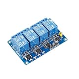
- This is a 4-channel 5V relay interface board, which can control various appliances and other equipment with large current, each need driver current of 15-20mA
- Note: This item is suitable for ages 14 and up
- Product type: RELAY
- Brand: SUNFOUNDER
These are runtime permissions. Request only those the app actually needs, handle denial, check that Bluetooth hardware exists, and handle the case where Bluetooth is disabled. A manifest pattern for a basic scanner-and-connector is:
<uses-permission
    android:name="android.permission.BLUETOOTH"
    android:maxSdkVersion="30" />

<uses-permission
    android:name="android.permission.BLUETOOTH_ADMIN"
    android:maxSdkVersion="30" />

<uses-permission
    android:name="android.permission.BLUETOOTH_SCAN"
    android:usesPermissionFlags="neverForLocation" />

<uses-permission
    android:name="android.permission.BLUETOOTH_CONNECT" />

<uses-permission
    android:name="android.permission.ACCESS_FINE_LOCATION"
    android:maxSdkVersion="30" />
The location declaration depends on the app’s actual behavior and Android version. Follow the current Bluetooth setup guidance rather than requesting every permission by default.
Connection flow
- Check whether Bluetooth hardware is available.
- Prompt the user to enable Bluetooth if necessary.
- Request the relevant runtime permissions.
- Find or select the paired HC-05.
- Connect using Bluetooth Classic serial.
- Enable outlet controls only after connection succeeds.
- Handle disconnection and show the state as unknown until it is confirmed again.
Do not use an HC-05 app’s Classic Bluetooth connection code for an UNO R4 WiFi or ESP32 BLE service without rewriting the communication layer.
Power-supply design
Use USB or a suitable regulated supply during low-voltage development. Do not build an improvised capacitive or transformerless mains supply. The Uno documentation supports USB at 5 V and recommends 7–12 V through the DC jack or VIN; directly applying power to the 5 V or 3.3 V pins bypasses regulation and can damage the board.
Account for the Arduino, HC-05, relay-board logic, and all four relay coils. Verify startup and transient current, provide useful margin, and check for voltage droop when several relays energize simultaneously. A small USB port or linear regulator should not be assumed to power four relay coils safely.
Failure-mode checklist
| Symptom | Checks |
|---|---|
| HC-05 is not discovered | Bluetooth enabled, permissions granted, module powered, module not connected elsewhere, and app using Classic Bluetooth rather than BLE. |
| App connects but relays do nothing | TX/RX crossed, common ground present, matching 9600-baud settings, correct serial object, adequate relay power, and correct polarity. |
| Relays operate backwards | Change one polarity constant or abstraction after testing with mains disconnected. |
| Relays click during reset | Check floating GPIOs, pull resistors, power droop, noisy wiring, and active-low defaults. |
| UI says on but load is off | Add acknowledgements, state queries, reconnection handling, and an explicit unknown-state display. |
| Appliance operates intermittently | Check contact rating, inrush current, terminal quality, coil power, electromagnetic interference, and brownouts. |
Testing matrix
| Test | Expected result |
|---|---|
| App starts with Bluetooth disabled | User receives a prompt or controls remain disabled. |
| No paired module | A clear connection error is displayed. |
| Module disconnects | The app shows disconnected or unknown state. |
| Arduino resets | All outputs return to a defined safe state. |
| Unknown command arrives | No relay changes and an error is returned in an extended protocol. |
| All-off command is sent | Every relay de-energizes. |
| Power is restored | The documented startup state is applied, preferably all off. |
| High-load appliance is connected | Only after rating, inrush, wiring, and enclosure suitability have been verified. |
Which platform should you choose?
| Platform | Best use | Main trade-off |
|---|---|---|
| Uno + HC-05 | Reproducing the reference project and learning serial relay control | Legacy Bluetooth workflow, hardware-serial conflict, and limited feedback |
| UNO R4 WiFi | Arduino-family BLE or Wi-Fi experimentation | Requires a different BLE/GATT design and attention to 3.3 V signals |
| ESP32 board | New projects needing BLE, Wi-Fi, web control, or Home Assistant integration | 3.3 V GPIO and more complex firmware architecture |
| Certified smart plug | Actual household use | Less educational flexibility, but avoids designing an exposed mains switch |
For a classroom or maker demonstration, Uno plus HC-05 remains understandable and inexpensive to prototype. For a new connected product, an ESP32-class board or UNO R4 WiFi is generally more capable. For routine household operation, a certified commercial power strip or smart plug is the safer choice.
Final recommendation
Build the four-channel controller as a low-voltage prototype, verify relay polarity and startup behavior, and make the Android app report acknowledged controller state. Do not treat the original tutorial’s relay board and enclosure as proof of safe mains construction. Only proceed to household AC after the switching components, supply, protection, enclosure, insulation, wiring, and local requirements have been reviewed by someone qualified to do that work.
The Tool Desk
Outbyte Driver Updater FREEFix the driver behind crashes, sound loss and screen glitchesFind Drivers →Outbyte PC Repair FREERepair Windows errors before they cause bigger problemsFix Now →Quick Recap
Product prices and availability are accurate as of the date/time indicated and are subject to change. Any price and availability information displayed on Amazon at the time of purchase will apply.