Some links on this page are affiliate links: if you buy through them we may earn a commission, at no extra cost to you.
The transition from petrol-powered construction and outdoor tools to battery-electric equipment is a system redesign, not a simple engine swap. The semiconductor system must manage battery energy, high motor currents, switching losses, heat, electromagnetic interference, charging, protection, and control response. Infineon’s offering brings these functions together through battery-management devices, MOSFETs, gate drivers, microcontrollers, charging electronics, sensors, connectivity, and security components.
For tool manufacturers and engineering teams, the value is a coordinated design platform—not a single chip or a turnkey certified tool.
As an Amazon Associate I earn from qualifying purchases.
The Tool Desk
Outbyte Driver Updater FREEScan for outdated or missing drivers - takes under a minuteDriver Scan →Outbyte PC Repair FREERepair Windows errors before they cause bigger problemsFix Now →What the semiconductor system includes
The topic comes from an Infineon-sponsored technical webinar about converting cordless power and garden tools from combustion engines to electric drives. The associated webinar description and Infineon’s battery-powered-tool portfolio describe a group of semiconductor functions that work together:
- battery monitoring, balancing, and protection;
- charging and power-conversion electronics;
- power MOSFETs for the motor inverter and battery disconnect;
- a three-phase gate-driver IC;
- an MCU running commutation or field-oriented control;
- current, temperature, position, and speed sensing;
- Bluetooth or Wi-Fi connectivity where required; and
- authentication and security functions for connected tools and batteries.
That portfolio can support the electronics required to design an electric tool. It does not directly convert any combustion-powered tool into an equivalent battery product, nor does purchasing one controller provide a motor, battery, charger, firmware, thermal system, or certification.
Why an engine replacement is an electrical and mechanical redesign
A combustion engine stores energy in fuel and delivers torque through a rotating engine, clutch, gearbox, airflow system, and speed-control mechanism. A battery-electric tool exposes the complete power path to electrical design limits:
#1 Best Overall
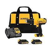
- Lightweight design fits into tight areas
- High performance motor delivers 300 unit watts out (UWO) of power ability completing a wide range of applications
- High speed transmission delivers two speeds (0-450 & 1,500 rpm) for a range of fastening and drilling applications
- 1/2' single sleeve ratcheting chuck provides tight bit gripping strength. Ergonomic handle delivers comfort and control
- Battery energy determines how long the tool can operate.
- Cell and BMS current capability determines whether the pack can supply short bursts and sustained load.
- The inverter converts DC battery power into controlled three-phase current.
- The motor and gearbox determine torque, speed, efficiency, vibration, and acoustic behavior.
- The controller must respond to triggers, jams, stalls, braking, and changing loads.
- The enclosure and cooling path must remove heat without making the tool too heavy or vulnerable to dust, water, and impact.
Consequently, an electric equivalent may require a different motor constant, gear ratio, battery voltage, cooling arrangement, trigger system, braking strategy, and enclosure. Semiconductor integration can reduce board area and interconnects, but it cannot remove losses in the motor windings, MOSFETs, copper, connectors, battery cells, or mechanical transmission.
Reference architecture
AC input / USB-C
        │
        ▼
   Charger stage
        │
        ▼
 Battery pack ──► BMS / monitoring / protection ──► DC link
                                                       │
                                                       ▼
 MCU / motor-control firmware ──► gate driver ──► 3-phase MOSFET inverter
        ▲                                      │
        └──── current / position / temperature feedback
                                                       │
                                                       ▼
                                               BLDC or PMSM motor
                                                       │
                                                       ▼
                                           gearbox / blade / bit / load
Optional blocks include a battery-disconnect MOSFET, DC-link capacitors, trigger sensing, thermal sensors, regenerative-braking management, Bluetooth Low Energy or Wi-Fi, and authentication circuitry.
The six essential semiconductor functions
1. Power switching
Six power MOSFETs normally form the three-phase inverter: one high-side and one low-side device for each motor phase. By switching these devices in a controlled sequence, the inverter creates the rotating magnetic field required by a brushless DC (BLDC) or permanent-magnet synchronous motor (PMSM).
Infineon identifies families including OptiMOS, StrongIRFET, CoolMOS, and CoolSiC for different voltage, efficiency, switching, and cost requirements. The correct device depends on the actual electrical and thermal envelope, not simply the tool’s nominal battery label.
Important MOSFET selection criteria include:
- maximum pack voltage plus switching transients;
- RDS(on) at the real gate-drive voltage and operating temperature;
- gate charge and switching losses;
- body-diode and reverse-recovery behavior;
- safe operating area and short-circuit robustness;
- package thermal resistance and heat-spreading options;
- electromagnetic-interference behavior at the intended switching frequency; and
- production availability and lifecycle status.
For systems at or above 36 V, Infineon describes a seventh MOSFET as an option for disconnecting the battery from the inverter during an overvoltage or other serious fault. It is a design option, not a universal requirement for every tool.
Do these 3 things before closing this tab:
1Repair Windows errors before they cause bigger problems2Scan for outdated or missing drivers - takes under a minute3Clear out junk files and repair common Windows errors2. Gate driving and current measurement
The MCU cannot usually drive the inverter MOSFET gates directly. A gate driver supplies the required gate voltage and source/sink current while managing high-side switching, dead time, protection, and fault reporting.
Rank #2

- Powerful 20 V Motor and 2 x 1.5 Ah Battery: Equipped with a robust 20 V motor and 2 Li-ion battery, this cordless drill delivers smooth power for various drilling and driving tasks;Its rechargeable battery ensures you're always ready for next project
- 2 Variable Speed Settings for Versatility: With two speed options (0-400, 0-1500 RPM ), this drill provides ultimate control over your applications; Perfect for both delicate tasks and heavy-duty jobs, you can easily adjust the speed to match your needs
- Robust 266 In-lb (30 N.m) Torque and 21+1 Settings: With a maximum torque of 266 In-lb (30 N.m) and 21+1 adjustable settings, this drill excels in precision and ease; It prevents over-tightening and protects your materials with its precise torque control
- Comprehensive 34-Piece Drill Kit: You’ll get a 20 V cordless drill with battery and charger, 4 wood bits, 4 twist bits, extension bar, flexible shaft, 10 short screwdriver bits, 10 long screwdriver bits, and a screw anchor set- all essentials in one set
- Effortless Precision with LED Illumination: Lightweight and user-friendly, this electric drill features an LED light to illuminate your workspace for precise drilling in dark or tight areas; Its effortless operation and intuitive controls make it perfect for both beginners and pros
The MOTIX 6EDL7141 is a three-phase gate-driver IC intended for battery-supplied BLDC and PMSM motor control. Infineon’s product information lists six gate-drive channels, three integrated current-sense amplifiers, adjustable source and sink drive current, integrated power supplies, programmable slew rate, and a 5.5–70 V operating-voltage range. Its stated supply-voltage range is 5.5–60 V; those figures should not be treated as interchangeable.
The device also provides configurable protection and more than 50 programmable parameters through SPI, according to Infineon. These settings allow a design team to tune switching behavior, efficiency, EMI, current sensing, and fault response. They do not replace board-level layout, firmware validation, or finished-tool testing.
3. Motor-control computation
The MCU reads current and rotor feedback, calculates the switching commands, processes the trigger, and coordinates protection and communications. It must also determine how the tool responds to a stall, jam, sudden load, low battery, sensor fault, or rapid deceleration.
Infineon’s MOTIX IMD700A and IMD701A integrate an XMC1404 ARM Cortex-M0 microcontroller with the 6EDL7141 gate driver in a motor-control system-in-package (SiP). The IMD70xA datasheet describes integration of the MCU, 60 V-class three-phase gate driver, synchronous buck converter, LDO, three current-sense amplifiers, protection functions, and configurable motor-control functions.
An integrated SiP can reduce PCB area, external interconnects, and BOM complexity. External power MOSFETs, DC-link capacitors, current paths, thermal paths, sensors, firmware, and compliance testing are still required.
4. Battery management
The battery-management system must protect the cells while allowing the motor to draw large transient currents. Depending on the pack design, it may provide:
Rank #3

- 【Power Drill Set】This power drill are perfect for DIY and home repairs
- 【20 V Electric Drill】This electric drill cordless has two Variable Speed (0-350/0-1350 rpm) and 18+1 torque settings
- 【Battery Drill Cordless】This cordless drill with battery and charger, 20 V 1.5 AH lithium-ion battery
- 【Compact Drill Design】The electric drill cordless is 2.5 pounds, power drills allow for easier protability
- 【Drill with Drill Bits】This drill set include 1*20 V Cordless Drill; 1*1.5 AH Battery; 1*Charger; 10*Bits(SL3-SL4-SL5-SL6-SL7-PHO-PH1-PH2-PH2); 1*Magneitc Bits Holder(60 mm); 10*Screwdriver Bits;
- individual cell-voltage monitoring;
- cell balancing;
- pack-voltage and current measurement;
- overvoltage, undervoltage, overcurrent, and short-circuit protection;
- overtemperature and undertemperature handling;
- charge and discharge cutoff;
- state-of-charge estimation; and
- communication with the tool and charger.
Infineon identifies 12 V, 18 V, 36 V, and 72 V as voltage classes served by its battery-powered-tool BMS portfolio. These are portfolio/application ranges, not a recommendation that every construction tool should use one of those exact pack voltages.
What’s actually slowing this PC down?
Pick the symptom - the matching free tool is one click away.
5. Charging
The charger is part of the safety-critical energy system. It must match the cell chemistry, series count, charge current, temperature limits, balancing strategy, communications protocol, regional input requirements, and enclosure thermal limits.
Infineon’s portfolio includes AC–DC charging devices, CoolMOS primary-side MOSFETs, OptiMOS secondary-side devices, EiceDRIVER gate drivers, CoolSET auxiliary power, USB-C ICs, and wireless-charging options. The charger, pack-side BMS, and tool-side motor electronics may communicate, but they have different electrical, thermal, and qualification requirements. A generic USB-C or universal charger should not be assumed safe for a tool pack without verifying the complete pack architecture and charging controls.
6. Sensors, connectivity, and security
Current, rotor position, speed, temperature, and pack measurements allow the controller to regulate torque and react to abnormal conditions. A trigger, interlock, or user-interface input must also be designed so that a tool cannot restart unexpectedly after a battery insertion, controller reset, or transient fault.
Bluetooth or Wi-Fi can support tracking, configuration, diagnostics, or fleet management. Authentication devices may be appropriate where a connected tool must distinguish approved batteries or accessories. These features add firmware, cybersecurity, power-consumption, and service responsibilities; they are not necessary for every cordless tool.
Understanding the inverter
Each of the three motor phases is connected to a half-bridge. The high-side MOSFET connects the phase toward the positive DC link, while the low-side MOSFET connects it toward the negative rail. The controller switches the devices in a sequence that produces torque.
Rank #4
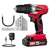
- Long-Lasting Battery for Occasional Users - AVID POWER 20V Lithium-ion battery pack comes with a real-time battery level display, which allows you to monitor charge status, so you're never caught off guard during projects. Perfect for homeowners who use a drill a few times a month. This drill can only use the battery from AVID POWER, please do not use a battery from other brand or a battery with a larger capacity
- Note: Regardless of whether you use it immediately, please fully charge the battery after receiving the product. When the machine is out of use, remove the battery from the drill and recharge it every 3 months for longer life
- 15+1 Torque Settings for Delicate Work - 15+1 torque (280 In-lbs) settings and variable speed (0-550 RPM) provide precise control for driving in/out screws to prevent stripping, and drilling into wood, drywall, plastics, and even metal with ease. Max torque for drilling into wood 13/16-Inch or steel plate 3/8-Inch. Note: this drill is Not suitable for more than 25mm drill bits and Not for Concrete/Masonry Walls
- Ergonomic & Lightweight Design: Compact, 2.5 lb lightweight build with a rubberized grip reduces fatigue during prolonged use, making it easy to handle even for first-time users. Built-in LED light illuminates dark workspaces like cabinets and tight corners for precise operation, while the 3/8” keyless chuck enables quick, tool-free bit changes to boost your home project efficiency
- Complete Ready-to-Use Kit - Includes 22 practical accessories: 10 drill bits, 10 driver bits, flexible shaft, and extension bar. Perfect for first-time owners tackling furniture assembly, wall mounting, or tight-space tasks
Dead time is required between turning off one device and turning on its complementary device. Insufficient dead time can cause shoot-through, creating a destructive short across the battery. Excessive dead time can increase distortion and diode conduction losses. Gate resistance, drive current, MOSFET gate charge, layout inductance, and switching frequency all affect the result.
The DC-link capacitors must be placed so that the high-current switching loop is short and low impedance. Gate loops and power loops should be treated separately, with careful attention to return paths, parasitic inductance, common-mode current, and sensor-reference integrity.
BLDC, PMSM, sensored, and sensorless control
BLDC control commonly uses trapezoidal commutation with Hall sensors or sensorless position estimation. PMSM control commonly uses sinusoidal control or field-oriented control (FOC). The 6EDL7141 product page lists both BLDC and PMSM applications.
Free tools Windows power users keep installed
One-click scans. No signup required.
| Choice | Strengths | Trade-offs |
|---|---|---|
| Trapezoidal BLDC control | Relatively straightforward control and lower computational burden | Potentially greater torque ripple, acoustic noise, and less smooth low-speed behavior |
| Sinusoidal or field-oriented control | Smoother torque, improved dynamic control, and potentially better acoustic performance | More demanding firmware, sensing, tuning, and validation |
| Sensored operation | Reliable rotor-position information, especially during startup and at low speed | Additional sensors, wiring, assembly, cost, and possible sensor failure |
| Sensorless operation | Fewer components and no rotor-sensor wiring | More difficult startup, stall detection, and operation under unusual loads |
For saws, trimmers, drills, grinders, and other construction equipment, trigger response, controlled braking, restart behavior, stall protection, and jam detection may matter more than steady-state efficiency alone. The appropriate strategy depends on the motor, load profile, acoustic requirements, cost target, and available feedback.
Independent reader supportYour contribution helps us test, update, and keep practical guides available for everyone.Voltage selection and power density
At a given mechanical power, a higher battery voltage can reduce current. That may reduce I2R losses in cells, busbars, connectors, wiring, and inverter conduction paths. However, higher voltage increases requirements for insulation, creepage, clearance, transient protection, switching ratings, pack safety, and service procedures.
There is no universally superior 18 V, 36 V, or 72 V architecture. Begin with required continuous and peak torque, speed, duty cycle, startup demand, runtime, weight, and user-handling constraints. Then verify whether the cells, BMS, MOSFETs, motor, wiring, connectors, and cooling system can support both peak and sustained operation.
Best Value
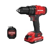
- 1/2inch Cordless drill/driver with high performance motor produces 280 unit watts out for completing a variety of applications
- 2speed gearbox with speeds of 0350/01, 500 for speed of fastening
- 1/2inches Keyless chuck for fast and easy bit changes
- Led light improves visibility in dark work areas
- Included 20V max Lithium battery with high performance cells provides ample runtime and increased performance
EMI, thermal design, and fault protection
EMI and switching speed
Faster switching can reduce some switching losses, but it also increases voltage and current slew rates. That can create ringing, radiated emissions, conducted noise, and common-mode current through motor cables, bearings, trigger wiring, and the enclosure.
Recommended Free Tools
The gate driver’s programmable slew rate can help balance switching loss against EMI. Infineon describes testing in a 3 m fully anechoic room against CISPR 14-1 for household appliances, electric tools, and similar equipment. Such a vendor demonstration or laboratory result is not certification of a finished construction tool. Testing must use the actual motor, cable lengths, gearbox, enclosure, battery, and mechanical load.
Thermal paths
Heat must be removed from the MOSFETs, gate driver, motor windings, battery cells, BMS switching devices, charger, connectors, and busbars. A compact SiP may reduce PCB area while concentrating heat in a smaller location. Thermal design therefore includes copper area, vias, package orientation, housing contact, airflow, potting or sealing materials, motor heat transfer, and battery placement.
Fault cases to validate
- motor stall or jam;
- phase-to-phase and phase-to-ground faults;
- MOSFET shoot-through;
- battery overcurrent or short circuit;
- battery overvoltage;
- overtemperature and undertemperature;
- sensor disconnection or implausible feedback;
- gate-driver undervoltage;
- loss of MCU control;
- trigger stuck on;
- motor overspeed;
- regenerative voltage during rapid deceleration; and
- battery insertion while the tool is active.
The 6EDL7141 provides integrated current-sense amplifiers and motor-control protection functions, but system-level safety depends on firmware, PCB layout, MOSFET selection, battery behavior, mechanical design, and validation.
Choosing an architecture
| Architecture | Best suited to | Main advantages | Main risks or limitations |
|---|---|---|---|
| Discrete MCU plus gate driver | Products needing maximum customization | Independent choice of MCU, driver, memory, peripherals, package, and safety architecture | More layout work, more interconnects, and potentially greater BOM complexity |
| Integrated motor-control SiP | Compact battery tools and faster prototypes | Smaller board, fewer external interconnects, and integrated control functions | Less flexibility and possible constraints in MCU resources, thermal placement, or supply continuity |
| Smart power module or integrated inverter | Designs prioritizing power-stage integration | Potentially simplified assembly and matched power components | Ratings, thermal interfaces, cost, and customization may not suit the tool |
| Sensored motor control | Tools requiring dependable low-speed startup and position control | Known rotor position and predictable startup | Extra hardware, wiring, and assembly effort |
| Sensorless motor control | Applications where reduced hardware is important | Fewer sensors and connections | More difficult startup, stall handling, and low-speed control |
An integrated SiP is not automatically cheaper, safer, or more reliable. The answer depends on production volume, firmware reuse, supply-chain strategy, thermal constraints, and the degree of customization required.
Quick wins for a faster PC:
Clear out junk files and repair common Windows errorsFree Scan →Scan for outdated or missing drivers - takes under a minuteDriver Scan →Validation checklist for a construction-tool design
- Define the load: specify mechanical output power, continuous and peak torque, speed, startup torque, duty cycle, stall duration, and runtime target.
- Choose the electrical architecture: establish pack voltage, cell arrangement, peak and continuous current, disconnect strategy, and DC-link voltage margin.
- Size the motor and gearbox: do not assume that the combustion engine’s motor, gear ratio, or torque curve has a direct electric substitute.
- Select the power stage: check MOSFET voltage margin, RDS(on) at temperature, gate charge, switching loss, body-diode behavior, safe operating area, and cooling.
- Design protection: define hardware and firmware responses to stalls, shorts, overtemperature, sensor faults, undervoltage, overspeed, braking, and stuck triggers.
- Control the EMI: optimize gate and power loops, dead time, DC-link placement, slew rate, grounding, shielding, and motor-cable routing.
- Test thermally: measure MOSFET, motor, battery, BMS, connector, and charger temperatures during both peak and realistic duty-cycle operation.
- Validate the pack and charger together: confirm cell limits, balancing, charge termination, temperature behavior, communications, and cutoff coordination.
- Test the complete tool: include the final enclosure, motor, gearbox, cable, battery, accessories, and mechanical load in EMC and reliability testing.
- Confirm production readiness: check component lifecycle, second-source strategy, firmware ownership, manufacturing tolerances, regional compliance, and service procedures.
Commercial and procurement considerations
These semiconductor products are primarily B2B design-in components. Development typically involves manufacturer technical resources, samples, evaluation boards, distributors, and engineering support rather than ordinary consumer retail purchasing.
The EVAL-6EDL7141-TRAP-1SH evaluation board can support prototyping around the 6EDL7141. Infineon’s IMD700A product page provides product information and sample or contact routes. Public stock and pricing signals can change by date, region, package, account, and quantity; they should not be treated as production quotations.
Infineon’s portfolio is a useful starting point for a coordinated design, but buyers should still compare discrete drivers, motor-control MCUs, BMS devices, smart power modules, and MOSFET families against voltage, current, safety, availability, firmware, and supply-chain requirements. A single-vendor portfolio can simplify integration while increasing supplier concentration.
Quick Recap
Product prices and availability are accurate as of the date/time indicated and are subject to change. Any price and availability information displayed on Amazon at the time of purchase will apply.

