Quick wins for a faster PC:
Repair Windows errors before they cause bigger problemsFix Now →Scan for outdated or missing drivers - takes under a minuteDriver Scan →This project is a low-voltage induction-heating experiment that uses a MOSFET-switched resonant circuit to heat a short length of nichrome wire. The nichrome becomes red hot and acts as the soldering element. It is therefore not a conventional soldering iron whose metal tip is heated directly by induction, and it is not a temperature-controlled commercial soldering station.
The design is an interesting educational prototype for experienced electronics makers. It is not documented well enough to treat as a finished handheld tool: the operating frequency, tip temperature, efficiency, thermal limits, EMC performance, and continuous-duty rating are not established. Build it to study resonant power electronics and magnetic coupling; buy a regulated soldering iron when dependable soldering is the goal.
As an Amazon Associate I earn from qualifying purchases.
What the project actually builds
A conventional soldering iron uses a resistive heater inside or around a metal tip. A temperature sensor and control circuit may regulate that heater so the tip maintains a predictable temperature.
The Tool Desk
Outbyte Driver Updater FREEFix the driver behind crashes, sound loss and screen glitchesFind Drivers →Outbyte PC Repair FREERepair Windows errors before they cause bigger problemsFix Now →This project takes a different route. A low-voltage DC supply drives a switching circuit, which creates a changing magnetic field through a ferrite output structure. That field couples energy into a nichrome wire. The nichrome wire heats by its own electrical resistance and becomes the hot working element.
#1 Best Overall

- Extreme Tinning: Fanttik T1 MAX is equipped with 4pcs tailor-made C210 (C210-I, C210-IS, 2pcs C210-K) rapid heating soldering tips, long service life, and anti-oxidation. Achieve a fast heating in 7 seconds, reduce the waiting time, and improve the efficiency of your repair tasks.
- Compatible DC/AC Modes: With the built-in 2600mAh battery in wireless mode, the maximum DC Output is 12W for up to 60 minutes at 840°F (450°C). Its small size is not bound by space, and maintenance work can be carried out anywhere. In wired mode, the maximum AC Output is 16W. It can be powered by a charger or mobile power supply with a Type-C port.
- Intelligent Gravity Sensing: After stopping working for 30 seconds, the soldering iron will enter sleep mode. T1 MAX will automatically restart to heat up to the temperature you set when picking it up again. NOTE: The red light flashes while heating, and the green light stays on when heating is complete.
- 6 Temperature Levels: The tail knob of the soldering iron has 6 levels for adjusting the temperature. Can be adjusted accurately and efficiently for different work scenes in the range between 390°F to 840°F (200°C to 450°C) so as not to damage heat-resistant components.
- Compact Structural with Stability: Equipped with an aluminum storage stand, the base tray can be pressed to pop up to store the welding head. The exquisite industrial design allows the soldering iron to be displayed on the table like an aesthetic piece, keeping the workbench clean, beautiful, comfortable, and pleasant.
That distinction matters. The documented build demonstrates an induction-coupled hot-wire soldering function, not direct induction heating of an ordinary soldering tip. It should also not automatically be compared with commercial “instant heat” transformer irons, which can use substantially different circuits and operating methods.
The original project is presented in eight steps and provides a schematic PDF named Schematic_Induction solder 1_2022-08-02.pdf and a PCB Gerber archive named Gerber_PCB_Induction solder 1_2022-08-29.zip. See the original Instructables project and the related Hackaday project page before attempting a reproduction.
How the circuit works
- DC input: The system is intended for a high-current, low-voltage supply, with the author recommending less than 15 V and a preferred current limit of 5 A.
- MOSFET switching: An IRFZ44N MOSFET switching stage alternates current through the magnetic and resonant network. The exact topology should be taken from the downloadable schematic rather than inferred from the abbreviated project description.
- Gate network: Fast-switching diodes and 10-kΩ and 470-Ω resistors are used in the gate-control and bias network described by the project.
- LC network: Two 1-µF polyester capacitors and a nominal 200-µH inductor form the documented resonant or filtering section.
- Ferrite output structure: A center-tapped ferrite winding couples the changing magnetic field to the nichrome load.
- Nichrome element: The coupled wire becomes red hot and supplies the heat used for soldering.
- Mechanical assembly: A pushbutton, high-current connector, handle, insulation, and a guard are needed to turn the electrical experiment into anything resembling a usable tool.
The nominal component values do not reveal the actual operating frequency. Resonance depends on the complete topology, parasitic capacitance and inductance, MOSFET behavior, ferrite material, winding geometry, and the load. The source does not publish a measured frequency, so it should be measured rather than guessed.
Parts and equipment
Published electrical parts
- IRFZ44N MOSFET
- Two 1-µF polyester film capacitors
- Nominal 200-µH inductor
- 10-kΩ and 470-Ω resistors
- Fast-switching diodes
- Pushbutton switch
- Nichrome wire
- High-current DC connector and suitably heavy wiring
- Custom PCB made from the supplied Gerbers
- High-current DC power supply
Useful test equipment
- Current-limited bench power supply
- Digital multimeter
- LCR meter for checking the inductor
- Oscilloscope, with appropriate probing technique, for checking switching waveforms
- Thermocouple, infrared thermometer, or thermal camera
- Fuse, emergency disconnect, heat-resistant insulation, and nonflammable mechanical supports
The project mentions a USB Type-C footprint but also says USB-C is unsuitable for the required current in this design. The precise limit depends on the connector, cable, power profile, and implementation; in any case, a generic USB charger, breadboard, thin jumper wires, or light-duty connector is not an appropriate substitute for a properly rated supply and wiring system.
Rank #2
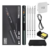
- 【High-Power Rapid Heating & Superior Temperature Control】This ALIENTEK T90 smart soldering iron supports PD3.1/QC3.0 fast charging with a wide power range of 18–140W, enabling 2.5–5 seconds ultra-fast tin melting. It adopts precision PID temperature control with an accuracy within ±2%, covering an adjustable temperature range of 80–450°C. Three one-touch preset temperatures (280°C / 350°C / 450°C) allow instant switching for different soldering scenarios, ensuring stable heat output and fast temperature recovery even for large solder joints and ground planes.
- 【Smart Digital Display & User‑Friendly Operation】Equipped with a 0.99-inch IPS LCD color screen (160×40 resolution), it clearly shows real‑time data including temperature, power, voltage, current, and hand‑held induction status. The interface is intuitive and high-contrast for easy reading in various environments. With simplified key control, you can quickly adjust temperature, power, and working modes; it also supports custom settings for sleep temperature, sleep time, and power levels, greatly improving operation efficiency for both beginners and professionals.
- 【Universal Compatibility & Portable Power Supply】Features a USB‑C power port supporting 9–28V wide voltage input, compatible with PD3.1/QC3.0 adapters, power banks, and other common power sources. It comes with a 140W 1.2m Type‑C cable and can automatically identify and match the maximum output power of the fast charger, or manually select 7 power gears for flexible use. The body is lightweight (about 55g) and compact, making it ideal for field repair, DIY projects, laboratory use, and mobile maintenance.
- 【Multiple Safety Protections & Durable Construction】Built‑in comprehensive safety systems including overcurrent protection, overheating protection, MOS tube abnormality detection, and heater resistance detection to ensure safe use and extend service life. It supports automatic sleep when idle to save energy and protect the soldering tip. The shell uses CNC-machined aluminum alloy with fine sandblasting for a comfortable grip, high durability, and effective heat insulation. The quick-lock sleeve design allows fast tip replacement, enhancing work efficiency.
- 【Full Model Compatibility & Wide Application】Available in T90A (T210 tip), T90B (T245 tip), T90C (T65 tip) versions to meet precision micro-soldering, conventional repair, and high-power large-joint work demands. Compatible with mainstream soldering tips in the market, offering strong replaceability. Perfect for electronic maintenance, PCB soldering, DIY electronics, model making, home repair, and industrial applications, providing stable and reliable performance for both hobbyists and professional technicians.
Making the inductors and output coil
The approximately 200-µH inductor
The documented construction uses a small round toroidal ferrite core, approximately 1 cm by 0.7 cm, wound with about 15 turns of 0.6-mm wire. The author reports an inductance of roughly 200 µH and uses 400-V polyester capacitors in the resonant network.
Those figures are construction notes, not guaranteed specifications. Ferrite composition, core dimensions, winding placement, wire insulation, measurement frequency, and saturation all affect the result. Measure the completed winding where possible. A nominal inductance reading at one test frequency does not prove that the part is suitable for the circuit’s ripple current or operating frequency.
The ferrite output structure
The output assembly uses a long ferrite cable core, such as one salvaged from an old laptop-charger or television cable, rather than simply any conventional toroid. The reported winding uses approximately 1-mm by 3-mm copper conductor, a center tap, two turns for the main section, and one additional turn for the output.
This is one of the least reproducible parts of the design. Salvaged ferrite cores can have very different permeability, loss characteristics, saturation limits, and frequency ranges. Physical resemblance is not enough. Follow the published diagram and construction images, then check the finished winding for continuity, shorts, secure insulation, and unexpected heating.
Rank #3

- Fast Heating & Adjustable Temperature - This digital soldering station heats up fast and has a wider temperature range (194℉~896) to choose from. The soldering iron can stay at the set temperature consistently with its PID temperature stabilization. This product conforms to the UL Standard (U.S.), [an Important Evaluation for Electric Appliances Safety].
- Space Saving – This compact soldering station helps save precious work space with an integrated soldering iron holder to provider greater space saving. The metallic protective mesh at the rear of the station prevents accidental contact with the soldering iron, and the mesh comes with soldering tip storage slots.
- Functions & Features – includes easy °C to °F conversion, Sleep Mode (5/10/30 mins adjustable), and Digital Temperature Calibration. All functions and temperature read-outs are displayed via a digital display, and accessed via a master control knob. The station enters sleep mode when non-use is detected for longer than the set duration to reduce unnecessary wear for the soldering tip and heating element.
- 12-IN-1 – This soldering iron kit includes the YIHUA 926 III Soldering Station, 2 Helping Hands, 6 Soldering Tips(YIHUA #1200/900M Series), Roll of Lead-free Solder Wire (35g), Solder Sucker, ESD Safe Tweezers, Solder Wire Dispenser, Cleaning Sponge.
- Choose YIHUA with Confidence – Enjoy our 12-month US- exclusive manufacturer technical coverage and 24/7 professional assistance on Amazon. Note: This model is designed to operate on 110-127V with a US-standard power plug.
PCB, wiring, and mechanical safety
The project says its PCB tracks were widened for high-current operation and recommends an aluminum PCB, but it does not provide a complete thermal analysis or a validated creepage-and-clearance review. A PCB that carries several amperes still needs an input fuse, adequate copper area, short current paths, strain relief, and connectors rated for both continuous and transient current.
The first version should not be treated as a finished handheld product. A practical revision needs a secure handle, heat-resistant or ceramic support for the nichrome, a guard against accidental contact, insulation from the workbench, and a nonflammable or suitably heat-resistant enclosure. A glowing wire can burn skin, ignite nearby material, oxidize, sag, become brittle, or short against another conductor.
Do not rely on the proposed USB-C footprint, breadboard contacts, thin test leads, or an ordinary low-current barrel connector. At 12 V, even 5 A represents approximately 60 W of input power. At 10 A, it represents approximately 120 W before losses.
Free tools Windows power users keep installed
One-click scans. No signup required.
A cautious commissioning procedure
- Inspect the board and windings. Look for solder bridges, damaged insulation, incorrect ferrite placement, loose high-current joints, and inadequate spacing.
- Verify component orientation. Confirm the MOSFET pinout, diode orientation, resistor values, switch wiring, connector polarity, and every connection against the published schematic.
- Check continuity and shorts. Verify that the supply rails are not shorted and that the inductor and output winding have the expected continuity. Film capacitors are non-polar, but their voltage, ripple-current, pulse, and temperature ratings still matter.
- Use a current-limited bench supply. Start at a conservative voltage with a fuse, short heavy-gauge leads, and an accessible disconnect. Keep the documented ceiling below 15 V and use 5 A as the author’s recommended limit, not as a certified rating.
- Power the circuit briefly without the nichrome. Watch input current, MOSFET temperature, capacitor temperature, and ferrite temperature. Stop immediately if current rises unexpectedly or a component heats rapidly.
- Check switching waveforms if possible. An oscilloscope can reveal failed oscillation, excessive ringing, poor gate drive, or operation far from the intended switching condition. Do not increase power merely because the circuit appears to switch.
- Do not leave it unloaded. The project reports approximately 1 A at 12 V without the output element and ferrite heating after about two minutes. No-load operation can still dissipate substantial power.
- Add the nichrome only after the unloaded behavior is understood. Mount it mechanically and electrically so it cannot touch the user’s hand, PCB, supply leads, workbench, or flammable material.
- Test in short intervals. Monitor current and temperature continuously. Stop if the MOSFET, capacitors, inductor, ferrite, connector, PCB, or handle becomes abnormally hot.
Reported results versus established results
| Item | Published report or recommendation | Evidence status |
|---|---|---|
| Supply voltage | Keep below 15 V | Author’s design recommendation |
| Preferred current limit | 5 A | Author’s recommendation, not a certified rating |
| Possible current | Up to 10 A under some conditions | Author’s report; wording does not clearly distinguish supply and output current |
| No-load current | About 1 A at 12 V | Author’s test |
| Ferrite heating | Begins after roughly two minutes | Author’s observation |
| Nichrome element | Becomes visibly red hot | Author’s observation |
| Operating frequency | Not stated | Unverified |
| Tip temperature | Not stated | Unverified |
| Efficiency | Not stated | Unverified |
| Temperature regulation | Not documented | Absent |
The project reports that the wire can produce a soldering result, but it does not publish calibrated tip temperature, warm-up time under a defined load, thermal recovery, maximum copper mass, continuous-duty testing, or comparison photographs against a conventional iron. The defensible conclusion is that it demonstrates a hot-wire soldering function—not that it performs like a regulated commercial station.
Rank #4

- 【Upgrade Technology】The soldering iron is upgraded 80W High Power, and can make the soldering iron quickly heat up within 20 seconds; This soldering iron can accurately adjust the temperature and a flexible temperature range of 180℃-480℃/ 356°F-896°F.
- 【Clear Digital Display】A high-definition LCD screen display, which indicates the temperature status more clearly, so you don’t need to worry about finding the right temperature for each welding job.
- 【Efficient Heat Dissipation and Anti-scalding Handle】The four ventilation holes on the solder tip provide better heat dissipation than others. Heat-resistant handle can insulate temperature effectively and is more suitable for long-term welding and repair work.
- 【Wide Application】widely used for welding circuit board, appliance repair, jewelry and metal headdress making, computer, and DIY. Very suitable for beginners, welders, basic household equipment, welding engineer training, etc.
- 【Must-have Soldering Iron Kit】Kit Includes soldering iron, tips,simple soldering iron stand, conventional sponge,solder wire,flux paste . A good basic soldering iron set that has all the materials you need to get started.
Likely failure modes
MOSFET overheating or failure
Incorrect gate drive, excessive switching loss, operation away from the intended resonant condition, high current, inadequate heatsinking, wiring inductance, voltage spikes, or a miswired output coil can destroy the MOSFET. Current-limited startup and waveform checks are more useful than simply installing a larger fuse.
Capacitor failure
A 400-V voltage rating alone does not establish suitability. The two 1-µF capacitors may experience significant ripple current and high-frequency stress. Replacements should be film capacitors intended for pulse or high-frequency service, with suitable ripple-current, temperature, and voltage ratings.
Ferrite saturation, loss, or cracking
Unsuitable salvaged ferrite, excessive flux, poor winding geometry, or overheating can reduce inductance and sharply increase switching stress. Stop if the core heats quickly, cracks, changes physically, or causes the input current to rise.
Outdated Drivers Are Slowing You Down
One free scan finds every outdated or missing driver and matches the right update for your exact hardware.Free scan · exact hardware matchWindows Errors? Fix Them Before They Spread
Repair common Windows errors and clear accumulated junk for a smoother, more stable PC - no reinstall needed.Free scan · no reinstallUnstable or failed oscillation
Incorrect MOSFET orientation, gate wiring, diode placement, winding connections, or excessive parasitic inductance can prevent the circuit from operating as intended. Do not troubleshoot by repeatedly applying full power. Return to continuity checks, verify the schematic connection by connection, and use a current-limited supply.
Best Value

- FLAMELESS PIPE SOLDER TOOL - The lack of an open flame allows this copper pipe soldering kit to be used anywhere. This soldering gun is Ideal for tight spaces where an open flame is not appropriate, and standard 1/2-inch heads are included.
- SAFER SOLDER - Solder copper pipes without the need for an open flame with this soldering-iron, which is great for jobs where conventional heating tools would be cumbersome, and precise control is needed.
- HEATS QUICKLY - This 115-volt pipe master tool plugs into a standard 120-volt outlet and quickly reaches a temperature of 950-degrees to heat copper pipes on all sides in a short time period, getting your soldering job done quickly and easily.
- EASY TO USE - All you need are the correct heads for your pipe size, readily available pipe solder and flux, or pre-soldered joints. Simply mount the heads around the pipe close to the joint, and in under 10 seconds, you'll have a perfectly sealed joint.
- PRODUCT DETAILS - Materials: Steel and Plastic. Dimensions: (L) 15” x (W) 4” x (H) 1”; Weight: 1.22lbs. Plug into Standard 120V Outlet. Heads Available for Pipes from 8mm - 22mm. Works on Both Integral Solder and End-Feed Fittings. Color: Orange.
Thermal and fire hazards
The red-hot nichrome is the most obvious hazard, but high-current faults can also vaporize traces, overheat connectors, and ignite insulation. The ferrite and switching components can heat even when the intended load is absent.
What would improve a second revision?
- Add temperature feedback using a suitably positioned thermocouple, thermistor, or other sensor.
- Implement overcurrent, overtemperature, undervoltage, and automatic timeout protection.
- Characterize switching frequency, gate waveforms, drain voltage, ripple current, input power, and useful heating power.
- Use a properly rated gate-drive arrangement rather than assuming the abbreviated resistor-and-diode network is adequate for every build variation.
- Specify ferrite material, core dimensions, winding geometry, and thermal limits instead of relying on salvaged parts.
- Use a guarded ceramic-supported heating element and a nonflammable enclosure.
- Add an input fuse, strain relief, robust connector, and clearly marked polarity.
- Measure actual tip temperature and recovery under defined soldering loads.
- Test several nichrome geometries and document duty-cycle limits.
- Provide a controlled shutdown path if the output coil is disconnected or the ferrite overheats.
Should you build it?
Build it if you already understand MOSFET switching, have a current-limited supply and measurement equipment, can measure inductance and current, and want to learn about magnetic coupling, resonant networks, and thermal design.
Do not choose it as your first soldering iron, for precision electronics assembly, lead-free work requiring controlled temperature, ESD-sensitive work, continuous production, or battery-powered portable use without a carefully designed power budget. The project has no documented temperature regulation, ESD behavior, EMC compliance, or safe continuous-duty rating.
A conventional temperature-controlled station or cartridge-style smart iron is the better tool when repeatability, tip-temperature stability, ESD control, and long work sessions matter. A commercial instant-heating or transformer iron may heat very quickly, but it is not necessarily temperature-controlled and is not equivalent to this low-voltage experiment. A commercial induction-heater module can reduce circuit-design work, but it does not solve the enclosure, thermal, electromagnetic, or handheld safety problems.
For reproduction, the project details page and the alternate project presentation can help locate the schematic and construction references. If you order a board from the supplied Gerbers, the original project names JLCPCB; historical promotional pricing on the project page should not be treated as a current offer.
Quick Recap
Product prices and availability are accurate as of the date/time indicated and are subject to change. Any price and availability information displayed on Amazon at the time of purchase will apply.

