Do these 3 things before closing this tab:
1Fix the driver behind crashes, sound loss and screen glitches2Repair Windows errors before they cause bigger problems3Scan for outdated or missing drivers - takes under a minuteThe simplest reliable design for an eight-drive external enclosure is a passive, direct-attach backplane connected to an external SAS HBA with two four-lane links: one link serves bays 0–3 and the other serves bays 4–7. Add a suitable PSU, front-to-back cooling, and optional SGPIO or SES sideband wiring for drive LEDs. An SAS expander is not required when the HBA already provides eight usable lanes.
Host computer
  └─ External SAS HBA
       ├─ External Mini-SAS link 1 → bays 0–3
       └─ External Mini-SAS link 2 → bays 4–7

8-bay enclosure
  ├─ Passive SAS/SATA backplane
  ├─ PSU → drives, backplane and fans
  ├─ Front-to-back cooling
  └─ Optional SGPIO/SES sideband for status LEDs
This guide covers the electrical, mechanical, thermal and host-side decisions needed to turn an eight-bay chassis or surplus server backplane into a working JBOD/DAS enclosure in which the host sees eight individual disks. It also explains where SATA and SAS compatibility ends, how to size power from startup current, and how to test or replace disks safely.
As an Amazon Associate I earn from qualifying purchases.
What you are building
DAS means Direct-Attached Storage. The enclosure connects directly to one host computer over a storage cable instead of exposing its disks over Ethernet. In a typical build, the external box contains no motherboard, processor, memory or operating system. It needs only the drive bays, backplane, power delivery, cooling and—if required—enclosure-management electronics.
Free tools Windows power users keep installed
One-click scans. No signup required.
The term JBOD is commonly used for an enclosure that presents individual physical disks to the host. JBOD does not mean that the data must be unprotected. The host can use ZFS, mdadm, Storage Spaces, Unraid or another software storage layer to create mirrors, parity arrays or other pools. The enclosure itself, however, does not provide redundancy. A failed PSU, backplane, cable, fan or HBA can affect several disks at the same time.
#1 Best Overall

- INCREASED PRODUCTIVITY: The 3-drive hot swap backplane lets you turn two 5.25in bays into a hot-swappable interface for you to connect up to three 3.5in SATA or SAS hard drives (HDD)
- MAXIMUM COMPATIBILITY: For added versatility, the hard mobile rack backplane can interface with SATA I/II/III and SAS I/II hard drives; An ideal accommodation for enterprise system applications; Power and status LEDs for each bay
- QUICK SETUP: For a quick and secure method of installing and removing drives, this trayless SATA hot swap backplane features individual ejection levers for each bay with a key-lock design for optional added security (includes two keys)
- MAINTAIN OPTIMAL TEMPERATURE: To help prevent drive failure, the 3-drive hot swap backplane features a vented solid aluminum enclosure that provides excellent heat dissipation in addition to a built-in fan with speed control; UL VO flammability rated
- THE IT PRO'S CHOICE: Designed and built for IT professionals, this 3-Bay hard drive backplane is backed for 2 years, including free lifetime 24/5 multi-lingual technical assistance
| System | What it normally does | Where storage decisions are made |
|---|---|---|
| DAS/JBOD | Connects directly to one host and exposes individual disks | Host operating system or storage software |
| NAS | Uses its own computer and network connection to provide files or block storage | NAS operating system |
| Hardware RAID enclosure | Uses a RAID controller and may expose logical volumes instead of individual disks | RAID controller |
| SAN | Provides block storage across a dedicated or specialized network fabric | SAN and host storage stack |
For an eight-bay enclosure, direct attach is usually the best starting point because it keeps the wiring and failure paths easy to understand. A direct-attach backplane with two four-lane connectors is documented in Supermicro’s eight-bay chassis examples, where each connector serves a group of four SAS/SATA bays. See the Supermicro SC835TQC-R802B specification and its direct-attach backplane explanation.
Start with a complete reference design
The following design is a practical baseline for eight 3.5-inch HDDs, eight 2.5-inch drives, or a compatible mixture of SATA and SAS devices:
| Part | Required specification |
|---|---|
| Chassis | Eight drive positions, rigid tray mounting and a front-to-back airflow path |
| Backplane | Passive SAS/SATA direct attach with two x4 Mini-SAS connectors for eight bays |
| Host adapter | External SAS HBA with eight usable lanes, preferably operating in IT, HBA or equivalent passthrough mode |
| Data cables | Two correctly matched external Mini-SAS cables, or documented internal-to-external cable assemblies |
| Power supply | Enough 12 V startup-current capacity, plus adequate 5 V capacity where required by the backplane and drives |
| Cooling | Fans that force air through the drive carriers and across the backplane and controller area |
| Management wiring | Optional SGPIO or SES sideband connection for activity and fault indication |
| Expander | Optional; normally unnecessary for exactly eight bays with an eight-lane HBA |
A Broadcom/LSI SAS9300-8e-class adapter illustrates the architecture: its product brief specifies two external SFF-8644 connectors, two x4 wide ports and 12 Gb/s SAS connectivity. The brief also lists 14.5 W nominal PCIe power and a 200-linear-feet-per-minute minimum airflow requirement for that adapter. This is an example of the required topology, not a claim that one specific older model is the best or most available controller for every build. Consult the Broadcom SAS9300-8e product brief for the exact card being considered.
Recommended Free Tools
Choose the drive format before buying the bays
3.5-inch bays
Use 3.5-inch bays for high-capacity hard disks, lower cost per terabyte and the conventional home-lab or backup enclosure. They are also the easiest option when reusing server trays, hot-swap cages and enterprise backplanes.
2.5-inch bays
Use 2.5-inch bays for SATA or SAS SSDs, compact systems, higher drive density or lower mechanical vibration. Check the drive carrier and backplane documentation rather than assuming that every 2.5-inch disk will fit. The documentation may distinguish 7 mm, 9.5 mm, 12.5 mm and 15 mm drives, and may list SATA, SAS or NVMe support separately.
For example, Chenbro’s SK62801 eight-bay 2.5-inch module has multiple backplane variants. The bay count alone therefore does not identify the supported drive protocol or thickness.
Understand SATA and SAS compatibility
SATA/SAS compatibility is a property of the entire path, not just a label on the enclosure. The controller, cable arrangement, backplane, expander if present, firmware and drive type all matter.
- A SAS HBA can generally communicate with SATA drives through a compatible SAS backplane, expander or breakout arrangement.
- A SATA-only controller cannot communicate with SAS drives.
- A SAS drive requires a SAS-capable controller and a complete SAS-capable data path.
- SATA drives are normally single-port.
- Many SAS drives are dual-port and can support redundant paths when the enclosure, controllers, cabling and operating system support multipath.
TrueNAS hardware guidance makes the practical distinction clearly: SAS controllers can support SATA devices through the appropriate mechanisms, but a SAS drive cannot be used in a SATA-only port. The same guidance distinguishes dual-port SAS multipath from ordinary single-port SATA operation.
Can SAS and SATA drives be mixed?
Sometimes, but treat mixed-drive operation as controller-, backplane-, expander- and firmware-dependent. A backplane may be electrically wired for both protocols without every mixed combination being validated by its manufacturer. Supermicro’s mixed SAS/SATA compatibility notice is a useful example of why the exact model documentation matters.
Before relying on a mixed pool, verify all of the following:
- The backplane explicitly supports both SAS and SATA.
- The HBA supports both types in its selected firmware mode.
- An expander, if used, supports the relevant SAS protocols and SATA STP behavior.
- The manufacturer documents or has validated mixed operation, rather than merely stating that the connector is compatible.
- SMART, enclosure management and hot-plug behavior work with both drive types.
Select the right backplane
For the reference design, choose an eight-position passive direct-attach SAS/SATA backplane. It should have two x4 Mini-SAS connectors, documented bay mapping, standard power inputs and optional sideband support.
Quick wins for a faster PC:
Scan for outdated or missing drivers - takes under a minuteDriver Scan →Repair Windows errors before they cause bigger problemsFix Now →A direct-attach connector is not one disk connection. A four-lane Mini-SAS connector carries four independent lanes, commonly serving four drive positions. The normal mapping is:
Backplane connector A, lanes 0–3 → bays 0–3
Backplane connector B, lanes 0–3 → bays 4–7
Confirm the actual mapping in the backplane manual. Bay numbering is not universal, and some manufacturers label connectors by port or lane group rather than by the front-panel bay numbers.
Passive versus expander backplanes
| Backplane | Advantages | Trade-offs |
|---|---|---|
| Passive/direct attach | Simple wiring, predictable lane mapping, no expander firmware and straightforward troubleshooting | Needs enough HBA lanes and usually two data cables |
| Expander-based | Allows many drives to share fewer upstream SAS lanes and may reduce the number of host cables | Adds firmware, power, heat, topology and another potential failure point |
| SATA-only | Adequate for an all-SATA design | Cannot accept SAS drives |
| SAS/SATA | Provides a flexible upgrade path when paired with a SAS HBA | Exact mixed-drive and management behavior still requires verification |
Look for the following before purchasing a used or surplus backplane:
- Backplane model and revision number.
- Eight actual drive lanes, rather than eight bays connected through an undocumented bridge.
- Connector type and port role.
- Drive-to-connector mapping.
- Supported SAS and SATA generations and drive types.
- Power connector type and voltage requirements.
- SGPIO or SES sideband header and pinout.
- Whether the board requires an expander, auxiliary power or a proprietary chassis controller.
- Whether power-reset, staggered spin-up or other management features depend on a motherboard.
Connector and cable guide
Mini-SAS connectors look similar enough to cause expensive mistakes. Match the connector, lane wiring, endpoint role and signaling generation—not just the physical shape.
The Tool Desk
Outbyte PC Repair FREERepair Windows errors before they cause bigger problemsFix Now →Outbyte Driver Updater FREEFix the driver behind crashes, sound loss and screen glitchesFind Drivers →Rank #2

- The transportation cycle is 10 to 15 working days.
- Product Name: 8 Bay SAS/SATA HDD hot-swap module
- Material: 2.1mm aluminum alloy+0.8mm SGCC
- Size: (L)147*(W)146*(H)84mm
- Backplane: 12Gb backplane with SFF8643 interface
| Connector | Typical use | Notes |
|---|---|---|
| SFF-8087 | Internal Mini-SAS | Four-lane internal connector used on older HBAs and backplanes |
| SFF-8643 | Internal Mini-SAS HD | Four-lane internal HD connector |
| SFF-8088 | External Mini-SAS | Older external four-lane connector |
| SFF-8644 | External Mini-SAS HD | External HD connector commonly used with 12 Gb/s SAS equipment |
| SATA 7-pin | Individual SATA data | One SATA data lane per connector |
| SGPIO sideband | LED and enclosure signaling | Separate management wiring; it is not ordinary drive data |
| SES | Enclosure management | Protocol used by some SAS backplanes and controllers to report status |
The SFF Committee identifies SFF-8644 as the shielded Mini Multilane 4/8X 12 Gb/s connector, commonly called Mini-SAS HD. See the SNIA-hosted SFF-8644 specification.
Cable-selection matrix
| Host-side connector | Enclosure-side connector | Correct approach |
|---|---|---|
| SFF-8644 | SFF-8644 | Straight external Mini-SAS HD cable |
| SFF-8644 | SFF-8088 | Documented SFF-8644-to-SFF-8088 hybrid cable |
| SFF-8088 | SFF-8088 | Straight external Mini-SAS cable |
| SFF-8643 or SFF-8087 | Internal backplane connector | Matching internal HBA-to-backplane cable |
| External HBA Mini-SAS | Four individual SATA ports | Forward breakout cable |
| Four SATA controller ports | One backplane Mini-SAS port | Reverse breakout cable |
A forward breakout cable carries one multi-lane HBA port to four drive-side SATA connectors. A reverse breakout cable combines four controller-side SATA ports into one backplane-side connector. Do not infer cable direction from the connector shape; confirm the wiring diagram or manufacturer part number.
If the HBA uses newer external connectors and the enclosure uses older SFF-8088 ports, use a documented hybrid cable. Broadcom lists SFF-8644-to-SFF-8088 cables for connecting newer external HBAs to legacy JBOD equipment in its SAS9300 documentation.
Use the shortest certified cable that reaches the enclosure. The safe length depends on connector generation, signaling rate, passive or active construction, and the exact enclosure design. A product-specific limit should not be generalized: for example, QNAP’s TL-D800S documentation and review describe a one-meter limit for that particular SATA-only design.
Choose the HBA and its operating mode
External SAS HBA
An external HBA is the cleanest choice when the enclosure is physically separate from the host. Select one with:
- External SFF-8088 or SFF-8644 ports.
- Eight usable direct lanes for a passive eight-bay backplane, or documented support for the chosen expander topology.
- Operating-system support for the host platform.
- IT, HBA, target or equivalent individual-disk mode when software-managed storage is planned.
- Adequate cooling in the host computer.
Two x4 external ports are sufficient for eight direct-attached drives because each port provides four lanes. The HBA does not need to be installed inside the enclosure; in the reference design it remains in the host, with only the Mini-SAS cables crossing between the two boxes.
Internal HBA with an external bulkhead
An internal HBA with SFF-8087 or SFF-8643 ports can work if the host and enclosure arrangement permits an internal cable or passive external bulkhead. A bulkhead is only a physical connector transition; it is not a protocol converter or expander. The cable assembly must preserve all lanes and use the correct endpoint wiring.
Hardware RAID controller
Use a RAID controller only when the desired result is hardware-managed RAID or when that controller has a well-supported HBA/JBOD passthrough mode. A controller that hides individual serial numbers, SMART data or physical disk identities is a poor fit for ZFS and similar software-defined storage.
What’s actually slowing this PC down?
Pick the symptom - the matching free tool is one click away.
Broadcom distinguishes IT firmware, which is intended to maximize connectivity and performance, from IR firmware, which provides limited RAID functionality. For software-managed storage, consult the exact controller documentation and prefer a supported IT or target-mode configuration. The TrueNAS CORE hardware guide also discusses HBA mode and Broadcom/LSI controller families.
Decide whether an expander is necessary
No expander is necessary for an ordinary eight-bay direct-attach build when the external HBA has two x4 ports and the backplane has two matching x4 inputs.
An expander is an active SAS routing device—effectively a SAS switch—not a RAID controller and not merely a passive SAS splitter. It allows more drives to be addressed through fewer upstream lanes. Broadcom’s SAS35x documentation lists SAS SSP, SMP, STP and SATA protocol support, with SAS rates of 3, 6 and 12 Gb/s and SATA rates of 3 and 6 Gb/s. Those capabilities still need to be confirmed for the exact expander and firmware. See the Broadcom SAS35x expander brief.
Choose direct attach when:
- The HBA has eight available lanes.
- The backplane has two x4 direct-attach inputs.
- The enclosure has exactly eight bays.
- Simple troubleshooting and clear fault isolation are priorities.
- The drives are SSDs and avoiding an upstream shared-link bottleneck matters.
Choose an expander when:
- The HBA has fewer than eight direct lanes.
- The backplane already includes a supported expander.
- One upstream cable is important to the mechanical design.
- The enclosure may grow beyond eight bays.
- You need SAS topology features such as supported dual-domain or multi-initiator operation.
| Direct attach | Expander topology |
|---|---|
| One x4 link commonly serves each group of four drives | Many drives share one or more upstream links |
| No expander firmware or expander heat | Requires expander power, cooling and firmware compatibility |
| Easy to identify whether bays 0–3 or 4–7 have a problem | More topology and zoning variables |
| Eight drives normally require two x4 data cables | Eight drives may be reachable through one x4 upstream cable |
| Best fit for a simple eight-bay build | Best fit for restricted port counts or future scaling |
Size the PSU from drive startup current
Do not choose the power supply from average operating wattage or from a generic recommendation such as 250–350 W. Hard disks can draw substantially more current while their motors start. The PSU must provide enough current on the relevant rail at the same time that all drives spin up, while also powering the backplane, fans and electronics.
Use this calculation:
Required 12 V startup current
= total drive 12 V startup current
+ backplane current
+ fan current
+ expander or auxiliary electronics current
+ design margin
For a worked example, the cited Seagate Exos X24 SATA manual lists a typical 12 V startup peak of 2.6 A for the specified model. Eight drives at that figure require:
Rank #3

- Turns 3x 5.25" bays into a hot-swappable interface for 5 x 2.5" and 3.5" SATA or SAS I/II & SATA I/II/III hard drives (HDD)
- 80mm cooling fan with full metal body for excellent heat dissipation
- Supports SATA 3.0 up to 6Gbps
- Support Raid 0,1,5,6,10(need Raid card)
- Cable: include 5pcs SATA cables
8 × 2.6 A = 20.8 A at 12 V
20.8 A × 12 V = 249.6 W on the 12 V rail alone
That is before adding fans, backplane electronics, conversion losses and transient margin. For eight high-capacity 7,200-RPM HDDs, a quality 400–500 W PSU may be a safer starting point than a small desktop supply, but that is not a universal answer. Calculate from the exact drive models and check the PSU’s 12 V amperage rating.
Power checklist
- Check both the total PSU wattage and the available 12 V current.
- Verify whether the backplane requires separate 5 V and 12 V rails.
- Confirm the backplane’s documented power connector and pinout.
- Use a quality PSU with transient margin.
- Check whether fans and an expander have separate current requirements.
- Use staggered spin-up only when the HBA, expander or backplane explicitly supports and documents it.
- Never mix modular PSU cables between manufacturers, even when the connector fits.
- Do not use an undocumented adapter or repinned PCIe power cable on a backplane.
Backplane documentation can show separate 5 V and 12 V requirements and additional drive power-reset circuitry. For an example, see the Supermicro BPN-SAS-801T-A3 manual.
Design the airflow before installing drives
The enclosure should pull cool air through the drive carriers, across the rear of the drives and backplane, and out through the rear. Do not rely on the fact that the room feels cool: the drive connectors, expander and HBA heatsink can still develop local hot spots.
- Place intake fans directly in front of the drive cage when possible.
- Use a rear exhaust path rather than recirculating air inside the chassis.
- Keep Mini-SAS and power cables out of the intake and exhaust stream.
- Provide airflow across any expander or controller installed in the enclosure.
- Leave the HBA heatsink unobstructed if it is in the host.
- Use fans with enough static pressure for the resistance of the drive cage and filters.
- Monitor temperatures after the enclosure reaches thermal equilibrium under load.
- Replace failed fans promptly; a silent fan can be a failed fan rather than a quiet one.
The Broadcom SAS9300-8e brief’s 200-linear-feet-per-minute figure applies to that specific adapter and operating condition, not to every SAS HBA. Use the exact controller’s thermal specification. TrueNAS SCALE hardware guidance likewise emphasizes keeping drives within the manufacturer’s operating-temperature limits and accounting for hot spots in dense enclosures.
Build the enclosure step by step
1. Inventory every part
Record the chassis model, backplane model and revision, drive form factor and thickness, HBA model and connector type, PSU rail ratings, fan voltage and current, sideband connector type, and both data-cable part numbers. Photograph the backplane before installation and label each connector and bay group.
2. Confirm the backplane topology
Read the actual backplane manual. Establish whether it is passive or expander-based, which connector serves each four-bay group, whether SAS and SATA drives are supported, whether mixed operation is validated, which power rails are required, and whether a sideband cable or proprietary controller is needed.
Do not rely on a marketplace listing that says SAS/SATA without locating the manufacturer’s documentation. A used server backplane may depend on a chassis-specific expander, fan controller or power harness.
3. Mount the backplane mechanically
- Disconnect AC power before installing or removing the backplane or its cables.
- Use the available mounting points so the board cannot flex when trays are inserted.
- Check every metal standoff for the correct position; an extra standoff can short the PCB.
- Confirm that trays seat squarely and that the drive connectors align with the insertion path.
- Ensure fans, trays and cables do not rub against each other.
Supermicro’s backplane safety instructions also require power to be disconnected before backplane installation or removal; see the backplane manual.
4. Install and test the cooling system
Install the fans before fitting drives. Confirm their airflow direction, startup behavior and connector polarity. Make sure air reaches the rear of the drive connectors and the HBA or expander area. If possible, test the fans independently before connecting the data paths.
5. Connect power
Use only cables whose pinout is documented for the PSU and backplane. Verify 5 V, 12 V and ground conductors. Check that the PSU has enough connectors and that any split harness does not exceed its current rating. Physically compatible connectors are not proof of compatible wiring.
6. Connect the two direct-attach data paths
External HBA port 0 → backplane port serving bays 0–3
External HBA port 1 → backplane port serving bays 4–7
Label both ends, for example HBA P0 / bays 0-3 and HBA P1 / bays 4-7. If the backplane is expander-based, connect the HBA to the expander’s documented upstream port and connect the downstream ports to the drive groups. Do not connect ports according to appearance alone; follow the expander manual.
Outdated Drivers Are Slowing You Down
One free scan finds every outdated or missing driver and matches the right update for your exact hardware.Free scan · exact hardware matchWindows Errors? Fix Them Before They Spread
Repair common Windows errors and clear accumulated junk for a smoother, more stable PC - no reinstall needed.Free scan · no reinstall7. Connect SGPIO or SES sideband if required
Drive data and LED management are separate projects. If the backplane requires SGPIO or SES, connect the correctly pinned sideband cable from the controller or HBA to the backplane. An ordinary SATA data cable does not carry SGPIO.
Intel’s enclosure-management cabling guide distinguishes the data connection from the SGPIO and fault-LED connection. A Supermicro backplane manual similarly states that SES-2 requires the backplane sideband cable.
Rank #4

- The transportation cycle is about 15 working days.
- Product Name: 8 Bay SAS/SATA HDD hot-swap module
- Material: 2.1mm aluminum alloy+0.8mm SGCC
- Size: (L)147*(W)146*(H)84mm
- Backplane: 12Gb backplane with SFF8643 interface
8. Test one drive in bay 0
With the enclosure powered off, install one known-good drive in bay 0. Power on and verify that it spins up and appears as one physical device. Check its model and serial number, and look for link resets or transport errors. Do not create a pool or array yet.
9. Test the second four-lane group
Move the known-good drive to bay 4, or use a second known-good drive there. This confirms that the second cable, HBA port and backplane port are functioning. Seeing exactly four drives after populating the enclosure is often evidence that one x4 path is absent or faulty.
Quick wins for a faster PC:
Scan for outdated or missing drivers - takes under a minuteDriver Scan →Clear out junk files and repair common Windows errorsFree Scan →10. Populate and document all eight bays
Add the remaining drives one at a time or in small groups. After each addition, record the physical bay, operating-system device path and drive serial number. Confirm the expected device count, temperatures and system logs before proceeding.
Validate the enclosure from the host
The examples below use Linux. TrueNAS, Unraid and Windows Server provide their own disk, pool, event-log and enclosure-management tools, but the same validation principles apply: detect every disk individually, confirm identity, check health, and review transport errors.
Confirm that the HBA is detected
lspci -nn | grep -i -E 'sas|scsi'The HBA should appear on the PCIe bus. Confirm its exact model and firmware personality with the vendor-supported utility for that controller generation. Do not assume that commands for sas2flash, sas3flash and storcli are interchangeable across controller families. For Broadcom/LSI adapters, consult the exact firmware and management documentation.
List individual disks
sudo lsscsi -g
lsblk -e7 -o NAME,PATH,SIZE,MODEL,SERIAL,TRAN,HCTL
Expect eight unique disk devices with correct capacities, models and serial numbers. The TRAN and HCTL fields can help identify the transport and host/channel/target/LUN path. The lsblk documentation describes these output fields and device discovery behavior.
Check SMART and health information
sudo smartctl --scan-open
sudo smartctl -x /dev/sdX
Replace /dev/sdX with the device being tested. SATA disks behind a SAS path may sometimes require -d sat for SMART access, while native SAS disks use their SAS/SCSI path. The smartctl manual documents --scan-open and the extended -x report.
Record each drive’s model, serial number, firmware revision, temperature, overall SMART result, reallocated and pending sectors for HDDs, uncorrectable errors, and any SAS transport or SATA PHY errors exposed by the device.
Watch the kernel and transport logs
sudo dmesg -TwLook for link resets, SCSI sense errors, CRC or SATA PHY errors, expander discovery failures, repeated device removal and re-addition, and HBA thermal or firmware messages. A correctly built enclosure should not repeatedly lose and rediscover drives while idle.
Run long tests carefully
sudo smartctl -t long /dev/sdXWhen the test has completed, run sudo smartctl -x /dev/sdX again. Run surface or long tests only on blank or safely isolated drives. Do not perform destructive testing on data-bearing disks, and do not start a long test on a disk in a degraded array unless the storage platform explicitly says it is safe.
Recommended Free Tools
Hot swap and drive replacement
A hot-swap tray is a mechanical feature, not an unconditional guarantee that removal is safe under every operating system and storage layer. Safe replacement requires support from the backplane, drive, HBA, operating system and the pool or RAID software.
- Identify the disk by serial number, not only by a volatile name such as
/dev/sdX. - Stop or offline the relevant filesystem, pool, RAID member, virtual-machine workload or application.
- Flush pending writes.
- Mark the disk failed or offline in ZFS, mdadm, Storage Spaces, Unraid or the applicable storage manager.
- Remove the disk from the operating system or controller if required.
- Confirm that the device has disappeared and that the remaining array is in the expected state.
- Pull the tray and remove the disk.
- Insert the replacement and allow the backplane to seat it fully.
- Rescan or wait for the HBA and operating system to detect it.
- Confirm the replacement serial number before starting a rebuild or resilver.
Linux provides SCSI removal and rescan interfaces, but there is no single universal hot-swap command for every HBA and driver. The Linux SCSI interfaces documentation describes these operations as transport- and driver-dependent.
For an unused Linux block device that has already been released by the storage layer, a common removal fallback is:
Best Value
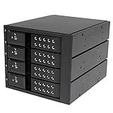
- INCREASED PRODUCTIVITY: The mobile rack backplane for 3.5in SAS II/SATA III turns three 5.25in bays into a hot-swappable interface for up to four 3.5” SATA or SAS hard drives (HDD)
- MAXIMUM COMPATIBILITY: The hot swap backplane for 3.5in SAS II/SATA III can interface with SATA I/II/III and SAS I/II hard drives, an ideal solution for enterprise system applications; Power and status LEDs for each bay
- EASY TO USE: For a quick and secure method of installing and removing drives, this trayless hot swap mobile rack backplane features individual ejection levers for each bay and a key-lock design (includes two keys)
- MAINTAIN OPTIMAL TEMPERATURE: To help prevent drive failure, the 4-drive hot swap backplane features a vented solid aluminum enclosure that provides excellent heat dissipation in addition to a built-in fan with speed control; UL VO flammability rated
echo 1 | sudo tee /sys/block/sdX/device/deleteFor a replacement disk, a typical SCSI host rescan fallback is:
echo '- - -' | sudo tee /sys/class/scsi_host/hostH/scanReplace sdX and hostH with the correct device and host. These commands do not replace offlining a disk in ZFS, mdadm, Storage Spaces or another storage manager.
Understand bandwidth limits
A 12 Gb/s SAS label identifies a signaling rate per SAS lane. It does not guarantee application throughput. The cited SAS9300-8e brief lists two x4 wide ports and a 9,600 MB/s half-duplex SAS bandwidth figure for its x8 configuration, but actual performance depends on the HBA, PCIe bus, cables, backplane, expander, drive type, queue depth, workload and filesystem. See the Broadcom specification.
- Eight HDDs will normally be limited by mechanical media performance before they saturate two SAS links.
- Eight SATA SSDs can expose limits in the HBA, PCIe bus, shared upstream link or expander.
- An expander can reduce aggregate bandwidth when many drives share one upstream x4 connection.
- A passive direct-attach backplane does not combine disks into a faster array; the host’s storage software performs that function.
Do not promise that eight drives will simultaneously achieve their individual maximum rates. The practical result depends on the workload and the slowest shared component.
Direct attach, expander and other design choices
External SAS HBA versus SATA-only controller
An all-SATA design can cost less and may use individual SATA data cables or a SATA backplane. It cannot later accept SAS drives. An SAS HBA costs more complexity up front but provides a standard external Mini-SAS path and a better upgrade route for SAS disks, dual-port SAS and enterprise backplanes.
PC Slower Than It Used to Be?
A free scan shows the junk files, broken settings and background clutter dragging Windows down - then fixes them in one click.Free scan · Windows 10 & 11Crashes, No Sound, or Screen Glitches?
Random freezes, missing sound and display glitches usually trace back to one bad driver. Find and replace yours safely.Free scan · under a minuteHBA mode versus hardware RAID
| HBA/IT mode | Hardware RAID mode |
|---|---|
| Presents individual disks to the host | May present logical volumes |
| Good fit for ZFS, mdadm, Storage Spaces and Unraid | Useful when controller-managed RAID and cache are specifically desired |
| Host software manages redundancy and rebuilds | Controller manages RAID metadata and rebuilds |
| Preserves direct access to disk serials and health information more readily | May hide disk identities or SMART data |
DIY versus prebuilt enclosure
| Option | Best for | Main compromise |
|---|---|---|
| DIY passive enclosure | Reusing surplus chassis, trays and backplanes; maximum flexibility | Requires mechanical, electrical, thermal and compatibility testing |
| Used server chassis | Integrated trays, PSU, fans and backplane | May be large, noisy or dependent on proprietary parts |
| New external JBOD | Fast deployment and vendor support | Higher cost and less freedom to reuse parts |
| Custom 3D-printed enclosure | Compact or unusual layouts | Requires extra attention to rigidity, drive retention, airflow, EMI and material safety |
A prebuilt SATA alternative such as the QNAP TL-D800S can be useful when SAS support is not required. Its documented architecture should not be treated as evidence that every eight-bay external enclosure supports SAS. Likewise, older DIY guides and product reviews can explain topology but may use obsolete connectors, firmware or pricing. For example, the ServeTheHome expander project is useful for concepts, while its external wiring guide should be cross-checked against current HBA and backplane manuals.
Troubleshooting by symptom
| Symptom | Likely causes | Next checks |
|---|---|---|
| No drives detected | No backplane power, wrong HBA mode, incorrect cable, absent expander power or unseated drive | Check PSU and HBA detection, test one drive, verify both endpoint connectors and read the backplane map |
| Exactly four drives detected | One x4 cable, HBA port or four-bay backplane group is missing | Swap the known-good cable and test bay 4; confirm the port-to-bay map |
| SATA works but SAS does not | SATA-only controller or backplane, unsupported breakout or incomplete SAS path | Confirm SAS capability at every active component; test the SAS drive on a known-good SAS HBA |
| SAS works but SATA does not | Expander lacks STP support, backplane qualification limit, cable issue or firmware problem | Verify STP/SATA support and test the SATA disk directly through the HBA |
| Random dropouts or CRC errors | Bad cable, loose latch, HBA overheating, PSU sag, vibration, damaged connector or expander firmware | Replace one component at a time and record whether the fault follows the cable, bay or HBA port |
| PSU shuts down during boot | Simultaneous HDD spin-up, inadequate 12 V current, wrong pinout or short circuit | Boot with one drive, then add drives progressively; verify rails, connectors and startup-current calculations |
| Drive LEDs do not work | Missing SGPIO/SES cable, pinout mismatch or unsupported enclosure management | Check the sideband manual and test activity and fault states with a known drive |
| Expander sees no downstream drives | Missing auxiliary power, wrong upstream/downstream port, firmware issue or bad cable | Verify port roles, power, firmware and airflow; test the passive path if available |
| Overheating | Insufficient airflow, blocked intake, high-resistance fan or cable obstruction | Measure drive temperatures at equilibrium and improve the path through the cage |
| Multipath behaves incorrectly | Single-port SATA drives, unsupported dual-domain backplane or incorrect host configuration | Use dual-port SAS drives and a documented multipath-capable topology only |
Use the failure pattern to isolate the fault
If all drives disappear, start with enclosure power, the HBA and the shared cable path. If one group of four disappears, concentrate on that x4 cable, HBA port and backplane connector. If the fault follows a cable when it is moved, replace the cable. If it follows the bay, inspect the backplane. If it follows the HBA port, investigate the controller or host PCIe slot. Change one item at a time so that the diagnosis remains meaningful.
SGPIO, SES and drive LEDs
Activity and fault LEDs do not automatically work because the drive data connection is present.
- SGPIO is sideband signaling commonly used to control drive activity and fault LEDs.
- SES is an enclosure-management mechanism used by some SAS backplanes and controllers.
- Some backplanes can display local activity but need sideband wiring for fault identification.
- Some HBA, operating-system and backplane combinations expose enclosure status; others expose only the disks.
Treat LED support as a separate compatibility test:
- Identify the backplane’s LED protocol.
- Confirm that the HBA or controller supports that SGPIO or SES path.
- Connect the correctly pinned sideband cable.
- Test activity and fault indication using a known drive.
- Always confirm a drive by serial number before removal; never rely on an LED alone.
Dual-port SAS and multipath
Many SAS drives have two independent SAS ports, but not every SAS model is dual-port. SATA drives are ordinarily single-port. Redundant paths require dual-port SAS drives, a dual-domain-capable backplane or expander, appropriate cabling, supported initiators and an operating system configured for multipath.
Do not connect two hosts or two HBA paths to ordinary SATA drives and expect safe failover. SATA devices have different port and STP behavior. The TrueNAS SCALE hardware guide and the T10 STP document provide useful background on these distinctions.
Final commissioning checklist
- Chassis is rigid and every tray seats correctly.
- Backplane model, revision, power requirements and bay map are documented.
- Backplane is passive direct attach or its expander topology is understood.
- HBA is SAS-capable, detected by the host and in the intended IT/HBA/JBOD or RAID mode.
- Both Mini-SAS data cables match their endpoint connectors and wiring direction.
- Port 0 maps to bays 0–3 and port 1 maps to bays 4–7, or the actual documented map is recorded.
- PSU 12 V startup current was calculated from the chosen drive datasheets.
- 5 V and 12 V rails are connected as required by the backplane.
- Fans provide front-to-back airflow and the HBA or expander receives adequate cooling.
- SGPIO or SES sideband wiring is connected only if its pinout and support are confirmed.
- All eight disks appear individually with the correct model, capacity and serial number.
- SMART information is readable and temperatures are acceptable.
- Kernel or system logs show no repeated resets, CRC errors or device dropouts.
- Drive removal has been tested only after the storage layer safely offlines a disk.
- There is a current record of bay number, drive serial number and operating-system identity.
- Backups exist; the enclosure is not being treated as a substitute for redundancy or backup.
Frequently Asked Questions
Do I need a SAS expander for an 8-bay DAS enclosure?
No. If the host has an external SAS HBA with two usable x4 ports and the backplane has two direct-attach x4 connectors, connect one port to bays 0–3 and the other to bays 4–7. Use an expander when the HBA has insufficient direct lanes, the backplane already includes one, or future expansion and reduced cable count justify the added complexity.
Can I use SATA and SAS drives in the same enclosure?
Sometimes, but verify the exact controller, backplane, expander and firmware documentation. A SAS HBA can generally support SATA drives through a compatible path, while a SATA-only controller cannot support SAS drives. Mixed-drive operation may be electrically possible without being vendor-validated.
The Tool Desk
Outbyte PC Repair FREERepair Windows errors before they cause bigger problemsFix Now →Outbyte Driver Updater FREEFix the driver behind crashes, sound loss and screen glitchesFind Drivers →Can a RAID card be used instead of an HBA?
Yes, if the card has a well-supported HBA, JBOD or passthrough mode and exposes the individual disks reliably. For ZFS, mdadm, Storage Spaces or Unraid, a genuine SAS HBA in IT or equivalent mode is usually the better fit because it preserves individual disk visibility.
Does a hot-swap tray make it safe to pull a disk while the enclosure is running?
Not by itself. First identify the disk by serial number, offline it in the filesystem, pool or RAID layer, flush writes and remove it from the operating system or controller as required. Then confirm it has disappeared before pulling the tray. The correct procedure varies by operating system and storage stack.
Why does my host detect only four of the eight drives?
The most common reason is that only one four-lane Mini-SAS path is connected or working. Check the second cable, HBA port, backplane connector and bay mapping. Test one known-good drive in bay 4 to isolate the second x4 group.
The Bottom Line
For a straightforward eight-bay SATA/SAS DAS, use a passive direct-attach backplane with two x4 Mini-SAS inputs and an external eight-lane SAS HBA in IT or HBA mode. Size the PSU from the chosen drives’ startup current, provide forced front-to-back airflow, and treat cable direction, mixed SAS/SATA operation, SGPIO/SES LEDs and hot swap as items to verify—not assumptions. Once every bay reports the correct serial number, SMART data is readable and the logs are clean, the enclosure is ready for the host’s filesystem, pool or software RAID layer.
Free tools Windows power users keep installed
One-click scans. No signup required.
Quick Recap
Product prices and availability are accurate as of the date/time indicated and are subject to change. Any price and availability information displayed on Amazon at the time of purchase will apply.