The right dust collector is the one that delivers enough airflow at the resistance of your actual duct system—not the one with the most impressive horsepower or maximum-CFM number on its label. To size a woodworking dust-collection system, calculate two design values: the greatest airflow your connected machines require at the same time, and the static-pressure loss along the system’s most restrictive path.
Then size the branch and main ducts to maintain a suitable conveying velocity, and select a collector whose performance meets both requirements. This approach prevents two common mistakes: buying a collector that cannot move enough air once connected, or installing oversized duct that allows dust to settle because the airflow is too slow.
As an Amazon Associate I earn from qualifying purchases.
The two numbers that determine dust-collector size
Your basic design target is:
- Maximum operating airflow: the combined CFM required by the machines that may run simultaneously.
- Worst-path static-pressure loss: the resistance created by the longest or most restrictive route from a machine hood to the collector.
The selected collector must meet or exceed both numbers under operating conditions. A collector that produces the required CFM with its inlet open may fall well short after you add a filter, separator, flex hose, elbows, blast gates, and ductwork.
This is why horsepower is not a sizing method. Motor horsepower can help distinguish broad classes of equipment, but it does not tell you how much air reaches the machine through your particular installation. Likewise, “maximum CFM” is often measured at or near an unrestricted collector inlet rather than at the machine.
#1 Best Overall
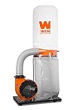
- Circulate up to 1,300 cubic feet of air per minute
- Attach up to two tools at a time with the dual 4-inch air inlets
- Vertical collection bag holds up to 50 gallons of dust
- 14-amp motor rotates the 10-inch steel impeller up to 3450 RPM
- Includes mobile base with four swivel casters for easy mobility
Step 1: Inventory every machine and calculate airflow
Start with the machine’s specified requirement
Make a list of every tool connected to the system:
| Machine | Port or manufacturer requirement | Will it run simultaneously? | Required CFM |
|---|---|---|---|
| Table saw | Use the manual or port-based estimate | Yes/no | — |
| Planer | Use the manual or port-based estimate | Yes/no | — |
| Router table | Use the manual or port-based estimate | Yes/no | — |
| Wide-belt sander or CNC router | Use the manufacturer’s application data | Yes/no | — |
The machine manual is the best source. If it does not state an airflow requirement, use a credible machine-flow table or estimate the airflow from the dust port. Treat a port-based estimate as a starting point, not a guarantee of adequate capture. Hood design, enclosure, leakage, and the type of chips or dust produced also matter.
Estimate airflow from a round port
For a round port, measure its inside diameter and use a suitable airflow table. The target is not simply the area of the port; the airflow must also create enough velocity to capture and transport the material.
Estimate airflow from a rectangular port
For a rectangular port, multiply its length by its width in inches, then multiply the area by 28:
Estimated CFM = port length (in.) × port width (in.) × 28
This estimates airflow at approximately 4,000 feet per minute (FPM). For example, a 3-by-5-inch opening has 15 square inches of area:
3 × 5 × 28 = 420 CFM
That result is an approximation. Use the tool manufacturer’s stated requirement instead when one is available, especially for enclosed machines, CNC equipment, sanders, and tools with multiple collection ports.
Apply the simultaneous-machine rule
If blast gates isolate inactive branches and only one machine operates at a time, size the system’s airflow target from the machine requiring the greatest CFM—not the sum of every machine in the shop.
Free tools Windows power users keep installed
One-click scans. No signup required.
If two or more machines can run at once, add their requirements:
System airflow target = CFM of machine 1 + CFM of machine 2 + ...
Also add the flows when a single blast gate serves multiple machines that may operate together. This rule is only valid when closed gates actually seal inactive branches. Leaky or poorly fitted gates allow air into unused branches and reduce the flow available at the operating hood.
It is appropriate to mention dust-collection blast gates as part of this calculation, but they are not a substitute for capacity. Their diameter should match the branch, and their resistance and leakage should be included in the system design.
Quick wins for a faster PC:
Repair Windows errors before they cause bigger problemsFix Now →Fix the driver behind crashes, sound loss and screen glitchesFind Drivers →Step 2: Size branch and main ducts for conveying velocity
The velocity target
Air must move fast enough to carry wood dust and chips through the duct instead of allowing them to settle. WOOD Magazine’s calculation method uses approximately 4,000 FPM for branch lines and approximately 3,500 FPM for the main duct. Its worksheet also uses 4,000 FPM as a simplifying design value. An Association of Woodworking & Furnishing Suppliers design handout identifies approximately 4,000 FPM as a minimum conveying velocity for dry wood dust and chips and presents airflow values at 4,500 FPM.
These are design guidelines, not a universal legal limit for every installation. The correct target can vary with the material, duct layout, hood, and applicable engineering or workplace requirements.
The airflow equation
Use this relationship to estimate a duct size:
CFM = duct cross-sectional area (square feet) × velocity (FPM)
For a round duct:
Area = π × diameter² ÷ 4
When diameter is in inches, convert the area to square feet before multiplying by FPM. Rearranging the equation gives an approximate starting diameter:
Do these 3 things before closing this tab:
1Clear out junk files and repair common Windows errors2Scan for outdated or missing drivers - takes under a minute3Repair Windows errors before they cause bigger problemsRank #2
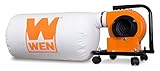
- 5.7-amp brushed motor combined with the 6-inch impeller moves up to 660 cubic feet of air per minute
- 4-inch dust port allows for connection to your favorite woodworking tools
- Compact design includes an onboard carrying handle for easy storage and transportation
- Measures in at 34.25 x 13 x 14.2 inches in size with a weight of 17 pounds
- Features lockable swivel casters, an optional wall mount, a 12-gallon 5-micron zippered collection bag, and a two-year warranty
Duct diameter (in.) ≈ √[4 × CFM ÷ (π × FPM) × 144]
The result is idealized. Friction, fittings, leakage, filter loading, and collector performance mean that the blower must do more work than this simple area-times-velocity calculation suggests.
Size each branch separately
Calculate each branch from the airflow needed by its machine. Do not automatically use the largest duct available on every tool.
For example, at 440 CFM, a 4-inch duct produces approximately 5,000 FPM, while a 5-inch duct produces approximately 3,200 FPM. The larger duct has lower velocity at the same airflow and falls below the approximately 4,000-FPM conveying target used in the WOOD example.
This does not mean a 5-inch duct is always wrong. It means the collector must actually deliver enough additional airflow to maintain the intended velocity, and the machine hood and port must be suitable for that arrangement.
Size the main duct for the flow it carries
The main duct must carry the greatest airflow required by the branches connected upstream of each section. A main near the collector may carry the flow of several simultaneously operating machines; a section beyond a branch split may carry only one machine’s flow.
Draw the duct layout and label the design CFM in every section. This prevents a common error: choosing one diameter for the entire main without checking how the required flow changes at each branch connection.
Step 3: Calculate the worst-path static-pressure loss
Static pressure is the resistance the collector must overcome. It is commonly expressed in inches of water column or inches of water gauge. The system’s total loss comes from every component between the machine and the collector.
The Tool Desk
Outbyte Driver Updater FREEScan for outdated or missing drivers - takes under a minuteDriver Scan →Outbyte PC Repair FREEClear out junk files and repair common Windows errorsFree Scan →For each possible machine-to-collector route, record:
- straight duct length;
- flexible hose length and diameter;
- 90-degree elbows;
- 45-degree elbows;
- wyes and branch entries;
- blast gates;
- reducers and transitions;
- cyclone or chip separators;
- filter and filter-cleaning condition; and
- any unusual hood, enclosure, or restriction.
Use equivalent length for fittings
A fitting disrupts airflow more than an equivalent length of straight duct. A practical worksheet converts each elbow, wye, gate, or other fitting into an equivalent length, then adds that length to the straight-run measurement.
For each branch:
- Measure the straight duct from the machine to the main.
- Count the 90-degree and 45-degree bends.
- Record wyes and branch fittings. In the WOOD worksheet method, a 45-degree wye connection is treated as a 45-degree bend for the branch calculation.
- Include the hose, gates, separator, and other restrictions.
- Use the applicable equivalent-length table to convert the fittings.
- Calculate the branch pressure loss at the design airflow.
Then calculate the main-duct loss from that branch’s entry point back to the collector. Add the branch and main losses for the complete route. Repeat the process for every machine and identify the route with the highest total. That highest value is the system’s design static-pressure loss.
Do not substitute a generic elbow count for a real calculation. A long run of flexible hose, a restrictive separator, a dirty filter, or an abrupt transition can change the result substantially. Flexible hose is especially important: use as little as practical, keep it stretched straight, and account for its resistance rather than treating it as equivalent to smooth rigid duct.
Windows Errors? Fix Them Before They Spread
Repair common Windows errors and clear accumulated junk for a smoother, more stable PC - no reinstall needed.Free scan · no reinstallOutdated Drivers Are Slowing You Down
One free scan finds every outdated or missing driver and matches the right update for your exact hardware.Free scan · exact hardware matchWhen building the system, compare 4-inch or 6-inch dust-collection hose and fittings by diameter, length, construction, and the resistance they add. The accessory is useful only if it preserves the calculated airflow; a larger-looking hose does not automatically improve a system whose collector cannot overcome its pressure loss.
Worked example: one machine at a time
Assume a small shop has three machines with the following design airflow requirements:
| Machine | Required airflow | Operating assumption |
|---|---|---|
| Table saw | 440 CFM | One machine active |
| Planer | 600 CFM | One machine active |
| Router table | 350 CFM | One machine active |
With sealed blast gates and only one machine operating at a time, the maximum airflow target is 600 CFM, because the planer requires the most air.
Rank #3
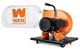
- Powerful 7.4-amp induction motor combined with the 9-inch impeller moves up to 600 cubic feet of air per minute
- 4-inch dust port allows for connection to your favorite woodworking tools
- Mount the unit to the wall of your shop for accessible dust collection whenever you need it
- Features an onboard carrying handle, swivel casters, a 15-gallon 5-micron zippered collection bag, and a two-year warranty
- Measures in at 43.3 x 17.7 x 20.1 inches in size with a weight of 41.1 pounds
Each branch is still sized for its own machine. The table-saw branch is designed around 440 CFM, the planer branch around 600 CFM, and the router-table branch around 350 CFM. The main section closest to the collector must be sized for whichever combination of branches may be open at the same time—in this case, 600 CFM if only one is open.
Next, calculate the static-pressure loss for each complete path. Suppose the planer is the longest route and includes a long rigid-duct run, several elbows, a blast gate, a length of flex hose, a separator, and the collector filter. Its completed branch-plus-main calculation is the highest of the three routes. The collector must deliver at least 600 CFM at that calculated pressure, not merely advertise 600 CFM at an unrestricted inlet.
Worked example: two machines at once
Now assume the table saw and router table may run together while the planer is isolated:
440 CFM + 350 CFM = 790 CFM
The airflow target becomes 790 CFM. The main duct must carry 790 CFM over the section shared by those branches, and the collector must deliver that flow at the static-pressure loss of the worst complete path under that operating arrangement.
If the shop later adds a sander requiring 900 CFM and allows it to run with the table saw, the relevant target becomes:
What’s actually slowing this PC down?
Pick the symptom - the matching free tool is one click away.
900 CFM + 440 CFM = 1,340 CFM
That is a different system. A collector adequate for the original one-machine layout may not be adequate after adding simultaneous operation, a longer duct run, a separator, or a finer-loaded filter.
Step 4: Read collector specifications without being misled
When comparing products, look for a fan curve or a CFM value stated at a specific static pressure. Record exactly where and how each number was measured:
- Maximum or inlet CFM: often measured with little or no system resistance.
- Shop-setting CFM: a manufacturer’s more realistic operating figure, though the test setup still matters.
- Machine-end CFM: airflow measured at the tool or hood after the duct system’s resistance.
- CFM at static pressure: the most useful comparison when the pressure value matches your calculated design point.
For perspective, Laguna’s published figures distinguish inlet and shop-setting airflow. Its B|Flux 1 is listed at 650 CFM at the inlet and 550 CFM in a shop-setting figure. The C|Flux 1 is listed at 1,314 maximum CFM and 900 CFM shop-setting airflow. Those differences are not a minor labeling detail; they show why an inlet number cannot be treated as delivered machine airflow.
Laguna lists the B|Flux 1 as a 1-HP-class collector with a 4-inch inlet, 550 shop-setting CFM, and 4.86 inches of water maximum static pressure. Its 1.5-HP C|Flux 1 is listed at 900 shop-setting CFM, a 6-inch inlet or two 4-inch ports, and 10.1 inches of maximum static pressure. The 5-HP X|Flux 5 is listed at 1,823 shop-setting CFM, 3,093 maximum CFM, an 8-inch inlet, and 12 inches of maximum static pressure.
Recommended Free Tools
These published examples illustrate the difference between collector classes; they do not establish that a particular horsepower always produces a particular usable CFM. Match the collector’s curve or operating data to your calculated system instead.
Industrial machines can require much more airflow. Laguna lists the I|Flux 5 Elite at 3,991 CFM at 5 inches of water column with a 12-inch inlet. The same manufacturer gives 1,500 CFM as an example minimum for a typical CNC router and 2,000 CFM for a typical 37-inch-wide-belt sander. Those are manufacturer application examples, not universal requirements for every CNC router or sander.
For a serious multi-machine, CNC, or wide-belt installation, consider a dust collection system design or industrial woodworking dust collector resource rather than assuming a consumer shop collector can be adapted to the job.
Components that change the calculation
Flex hose
Flex hose is convenient at the machine, but its internal ridges and length increase resistance. Keep runs short, avoid unnecessary loops, and use a diameter appropriate to the branch and hood. Include all hose in the pressure-loss worksheet.
Quick wins for a faster PC:
Clear out junk files and repair common Windows errorsFree Scan →Scan for outdated or missing drivers - takes under a minuteDriver Scan →Repair Windows errors before they cause bigger problemsFix Now →Blast gates
Blast gates make the one-machine-at-a-time assumption possible by isolating inactive branches. They must close tightly, remain accessible, and match the duct diameter. A gate that leaks or is left partly closed changes the airflow and pressure assumptions.
Rank #4

- 【HIGH EFFICIENCY】 Our DEWALT high efficiency dust separator can capture wood chips and other debris before they enter your vacuum cleaner, reducing suction loss due to clogged vacuum filters. Saves you the cost and time of expensive filter and dust bag replacement.
- 【WIDE APPLICATION】 This dust separator applies to most materials: wood chips, drywall dust, concrete dust, clay silica dust, soda water, cooling ash and soot, water, metal shavings, baking powder, grass and leaves, pets hair, drug waste and more.
- 【COMPATIBLE DESIGN】 The four-caster base of the dust collection system makes it very stable and easy to move around the workshop. Our 6 gallon shop vacuum system barrels are easy to empty. With 1-7/8" or 2-1/2" port, it can be used with most vacuum cleaners, such as household vacuum cleaners, industrial vacuum cleaners, sweepers, etc.
- 【PREMIUM MATERIALS】 All included parts are made of durable, high-quality and heat resistant materials with anti-clogging design for optimum efficiency.
- 【WHAT YOU GET】1 x DEWALT dust separator, 1 x 6 gallon poly bucket (vacuum cleaner not included), 2 x Hose Holder, 1xLid, 2 x Lid Sealing Strip, 2 x Lid Latch, 2 x Handle, 1 x 1-7/8" Hose, 1 x Wheel Bracket, 4 x Caster bushing, 4 x Screws (3.9 * 16 F), 4 x Screws (4.8 * 16 F),1 x 3 years limited warranty.
Wyes and elbows
Use smooth, long-radius bends where possible. Count every bend and branch fitting, including fittings hidden behind machines or above a ceiling. A short-looking layout can still have high resistance if it contains several abrupt turns.
Separators and cyclones
A cyclone or chip separator can reduce the material reaching the collector filter and may improve maintenance, but it adds pressure drop and requires adequate capacity. Include the separator in the worst-path calculation. A cyclone dust separator for woodworking is therefore a system component to size—not an automatic airflow upgrade.
Filters and collection bags
Filter loading raises resistance and reduces airflow. Check the collector’s filter area, cleaning method, filtration specification, collection capacity, and replacement availability. Keep the filter clean according to the manufacturer’s instructions and replace damaged or saturated components. A nominal micron rating by itself does not make a shop dust-free or prove that exposure is controlled.
Recommended Free Tools
Airflow is not the same as capture effectiveness
A collector can meet a calculated CFM target and still provide poor capture if the hood is badly shaped, the machine is open to the room, or the duct connection leaks. Capture occurs at the source. Enclosures, close-fitting hoods, properly positioned pickup points, and sealed connections can matter as much as the blower rating.
NIOSH table-saw control research found that a properly designed auxiliary exhaust hood reduced wood-dust emissions by more than 90% in laboratory testing on a typical table saw. That finding does not promise the same reduction in every shop, but it demonstrates why source capture deserves equal attention with collector size.
Health and safety: dust collection is an engineering control
Wood dust can enter through inhalation and contact with the skin and eyes. NIOSH identifies irritation, respiratory hypersensitivity, asthma, and potential occupational carcinogenicity among the hazards associated with wood dust exposure.
OSHA identifies exhaust ventilation with collectors located at dust-generation points as a preferred engineering approach. Its ventilation requirements call for exhaust systems to maintain enough volume and velocity to gather dust and convey it to safe disposal without dispersing harmful quantities into the work area.
What’s actually slowing this PC down?
Pick the symptom - the matching free tool is one click away.
Meeting a CFM number does not guarantee a safe exposure level. Exposure also depends on hood geometry, enclosure, leaks, filter condition, maintenance, cleanup practices, ambient-air filtration, and the material being machined.
Use local exhaust at the tool, keep the system maintained, and avoid sweeping settled dust into the air. An ambient-air cleaner can supplement source capture but cannot replace it. Respirators are supplemental protection, not a reason to tolerate inadequate local exhaust. Anyone relying on respiratory protection should use an appropriately selected NIOSH-approved respirator within a compliant respiratory-protection program; a NIOSH-approved particulate respirator for wood dust should not be presented as a standalone dust-control solution.
A practical collector-selection checklist
- List every machine and obtain its airflow requirement from the manual where possible.
- Identify simultaneous operation. Add the airflow of machines that can run together; otherwise use the largest single requirement.
- Measure the ports and hoods. Treat port-area estimates as approximations.
- Draw the layout. Mark every branch, main section, gate, elbow, wye, hose, separator, and filter.
- Choose branch diameters that preserve an appropriate conveying velocity at the required branch CFM.
- Choose main diameters from the flow carried by each main section, not from a single shop-wide guess.
- Calculate the worst path using straight lengths and equivalent lengths for fittings and restrictions.
- Compare collectors using delivered performance. Prefer CFM at a stated static pressure or a performance curve.
- Verify the physical details: voltage, phase, inlet size, filter area and rating, collection capacity, bag or bin availability, noise, footprint, and filter-cleaning method.
- Check the operating point after installation. Inspect airflow, leaks, filter loading, and machine-end capture rather than assuming the label tells the whole story.
For a central collector purchase, compare a woodworking dust collector rated for CFM at static pressure only after you have established the machine list and duct layout. The correct model depends on the complete system, not on a universal horsepower recommendation.
When to escalate the design
Get specialist engineering or manufacturer assistance when the system has long duct runs, several simultaneously operating machines, large CNC routers, wide-belt sanders, combustible-dust concerns, unusual materials, or a commercial workplace subject to applicable codes and occupational-exposure requirements.
Free tools Windows power users keep installed
One-click scans. No signup required.
Do not generalize from a small collector’s shop-setting specification to an industrial application. Conversely, do not install an industrial-size main duct on a small collector without checking that the blower can maintain conveying velocity and overcome the resulting system resistance.
Source notes
The calculation method described here follows the updated WOOD Magazine treatment dated January 2, 2025, which builds on a method originally published in the magazine’s December 1999 issue. Manufacturer specifications and application examples are identified as such. The health and safety discussion reflects guidance and research from OSHA and NIOSH, including NIOSH’s wood-dust hazard information and table-saw source-capture research.
Frequently Asked Questions
Is horsepower enough to choose a dust collector?
No. Horsepower does not directly tell you the airflow delivered through your duct system. Choose a collector using CFM at a stated static pressure or a performance curve, then compare it with your calculated airflow and worst-path pressure loss.
Should I add the CFM of every machine in the shop?
Only if those machines can operate simultaneously or share an open branch. With sealed blast gates and one active machine at a time, use the largest individual requirement. Add the requirements of machines that may run together.
Does a larger duct always improve dust collection?
No. At a fixed CFM, a larger duct reduces air velocity. If velocity falls too low, dust and chips can settle. Duct diameter must be matched to the airflow the collector can actually deliver.
Does a 1-micron filter make a woodworking shop dust-free?
No. Filter rating is only one part of exposure control. Source-capture hood design, enclosure, duct sealing, filter condition, maintenance, cleanup, and ambient filtration also matter.
What is the difference between inlet CFM and shop-setting CFM?
Inlet or maximum CFM is commonly measured with little system resistance. Shop-setting CFM is intended to represent a more realistic operating condition, although the test setup still matters. Neither number automatically equals the airflow reaching your machine.
The Bottom Line
Work backward from the machine: determine the largest simultaneous airflow, size each duct section to preserve conveying velocity, calculate the highest static-pressure path, and choose a collector whose delivered performance clears both thresholds. The complete machine-to-collector system—not the bare collector inlet—is the unit that must work.
Quick Recap
Product prices and availability are accurate as of the date/time indicated and are subject to change. Any price and availability information displayed on Amazon at the time of purchase will apply.