You can build a small Arduino RFID lock demonstrator with a compatible RFID reader, card or tag, Arduino-compatible board, and a servo that moves a simple latch. The reader supplies a card’s identifier to the sketch; the sketch checks whether it is authorized and, in the example described below, briefly moves the servo. This is a learning prototype—not a tested or certified lock for a home or commercial exterior door.
How an Arduino RFID lock works
- A compatible card or tag is presented to the reader.
- The reader passes the card’s identifier to the Arduino.
- The sketch compares that identifier with an authorized value stored in the code.
- If it matches, the sketch operates the actuator—for example, moving a servo latch for a set interval.
An Arduino Project Hub example describes this UID-comparison and timed-servo approach: RFID-Based Smart Servo Lock System using Arduino UNO R4 Wi-Fi. That is an explanation of the example’s logic, not evidence that UID checking alone makes a lock secure.
As an Amazon Associate I earn from qualifying purchases.
Parts for a small demonstrator
A published Arduino Project Hub build lists an Arduino Uno Rev3, RFID-RC522 reader, additional RFID cards, SG90 micro-servo, jumper wires, breadboard, and 16×2 I2C LCD. The LCD is optional feedback; it is not needed for the basic read-and-actuate sequence. See the project component list.
The Tool Desk
Outbyte PC Repair FREERepair Windows errors before they cause bigger problemsFix Now →Outbyte Driver Updater FREEScan for outdated or missing drivers - takes under a minuteDriver Scan →- Controller: An Arduino-compatible board that matches the sketch and its pin mapping.
- Reader: An MFRC522/RC522 module. Confirm the breakout board’s supply and signal requirements rather than assuming every module is wired identically.
- Credentials: Cards or tags compatible with the reader’s supported protocol; “RFID” or “NFC” on a label does not by itself establish compatibility.
- Actuator: A small servo for a lightweight demonstration latch. An SG90 is not a full-sized door lock.
- Prototype materials: Breadboard and jumper wires for a temporary bench setup.
Reader and card compatibility
NXP’s MFRC522 data sheet describes the IC as a contactless reader/writer operating at 13.56 MHz and supporting ISO/IEC 14443 A, MIFARE, and NTAG. Those specifications apply to the IC; they do not guarantee compatibility with every card or breakout sold as RFID or NFC. Check the actual module and credential specifications before buying or wiring parts. See the NXP MFRC522 data sheet.
#1 Best Overall
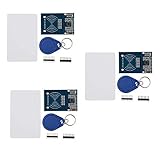
- The MF522-AN module design the circuit of card read by using the original Philips MFRC522 chip.
- Easy to use, low cost, and applicable to equipment development and card reader development etc.
- Applicable for the user who need to design or manufacture the RF card terminal.
- The module can be directly loaded into the various reader molds.
- The module use a voltage of 3.3V, it can connected communication with user's any CPU mainboard through several lines of SPI interface, it can ensure stable and reliable work, and reader distance.
NXP Technical Support stated in a 12 September 2023 support discussion that the MFRC522 was no longer supported and recommended the CLRC663 plus family for new designs. This is dated support-thread guidance, not a live product-status notice; consult NXP’s discussion and verify current status before starting a new design.
Choose the actuator architecture
A servo latch and a relay-switched electromagnetic lock are different systems, not interchangeable devices to connect to an unspecified Arduino pin. One is a small mechanical demonstration; the other switches a separate lock load through a relay. A tutorial illustrates the latter pattern: Arduino RFID electromagnetic lock.
Rank #2
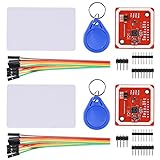
- RFID reader/writer supports: Mifare 1k, 4k, Ultralight, and DesFire cards, ISO/IEC 14443-4 cards such as CD97BX, CD light, Desfire, P5CN072 (SMX), Innovision Jewel cards such as IRT5001 card, FeliCa cards such as RCS_860 and RCS_854
- On-board level shifter, standard 5V TTL for I2C and UART, 3.3V TTL SPI
- Support NFC RFID reading and writing, P2P communication with peers
- Support I2C, SPI and HSU (High Speed UART), easy to change among these modes
- Small Size and easy to embed into your project
| Consideration | Servo-driven latch | Relay-driven electromagnetic lock |
|---|---|---|
| Typical role in the cited examples | Small servo moving a demonstration latch (Arduino Project Hub: component list). | Electromagnetic lock switched through a relay (ArduinoGetStarted.com: tutorial). |
| Mechanical fit | Requires a latch geometry the servo can move; the cited parts list does not establish suitability for a full-sized door. | Requires an appropriate lock, mounting arrangement, and door/frame fit; the cited tutorial does not establish a complete installation design. |
| Electrical design | Confirm the servo’s supply and current needs and the board’s signal/power arrangement. | Confirm the lock’s rated supply and current and use a suitably rated switching arrangement; the tutorial is not a universal circuit specification. |
| Power-loss behavior | Depends on the latch mechanics and how they behave without servo power; evaluate the actual mechanism. | Depends on the specific lock and its power arrangement; determine the required behavior rather than assuming it. |
| Appropriate scope here | Bench, box, or other small-scale learning demonstrator. | A distinct project architecture; real-door use needs a properly designed and evaluated access-control installation. |
Wiring and programming: verify the exact parts
The cited examples establish project patterns, not one circuit that is safe and correct for every combination of Arduino board, reader breakout, servo, relay, and lock. Before wiring, use the documentation for the exact parts to verify pin mapping, supply voltage, signal levels, actuator current, and switching requirements. Do not power a lock or other high-load actuator from an Arduino output pin unless the component documentation explicitly supports that arrangement.
In the servo demonstration, the sketch’s essential decision is whether the scanned UID matches an authorized value; a match triggers the servo action. Treat this as a way to learn about reading credentials and controlling an actuator, not as an access-control security design. Keep mechanical movement unobstructed on the bench and disconnect power before changing wiring.
Rank #3
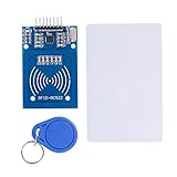
- The RF IC Card module design the circuit of card read by using the original Philips MFRC522 chip
- Easy to use, with pin header. The module can be directly loaded into the various reader molds.
- Applicable for the user who need to design or manufacture the RF card terminal.
- Module Interface: SPI, Data transfer rate: Maximum 10Mbit/s.
- Power Voltage : 3.3V,Operating frequency: 13.56MHz.
Why this is not a proven primary door lock
The cited project examples and MFRC522 data sheet do not provide independent security testing, reliability testing, lock certification, or a real-door egress assessment for the assembled DIY system. A reader specification describes supported communications; it does not validate the system’s resistance to unauthorized entry or failure. A UID comparison in a sketch should not be treated as proof that a credential cannot be copied or that the installation is secure.
For a residential or commercial entry door, use an appropriately evaluated access-control product and qualified installation rather than relying on this hobby build as the only security control. The sources do not establish egress or installation requirements for any particular door, so those must be resolved for the actual site and applicable requirements.
Quick Recap
Best Value
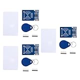
- MF522 - AN Module: Uses original Philips MFRC522 chip to design card reading circuits.
- Usability and Cost: Easy to use, low cost, suitable for device and card reader development.
- User Suitability: For users needing to design or manufacture RF card terminals.
- Module Installation: Can be directly installed in various reader molds.
- Connection and Performance: Operates at 3.3V, connects and communicates with any CPU mainboard via SPI interface, ensures stable and reliable operation and card reader distance.
Rank #4
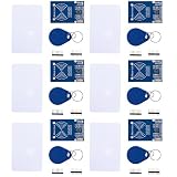
- MF522 - AN Module: Uses original Philips MFRC522 chip to design card reading circuits.
- Usability and Cost: Easy to use, low cost, suitable for device and card reader development.
- User Suitability: For users needing to design or manufacture RF card terminals.
- Module Installation: Can be directly installed in various reader molds.
- Connection and Performance: Operates at 3.3V, connects and communicates with any CPU mainboard via SPI interface, ensures stable and reliable operation and card reader distance.
Product prices and availability are accurate as of the date/time indicated and are subject to change. Any price and availability information displayed on Amazon at the time of purchase will apply.