Recommended Free Tools
Yes—you can control a hobby servo without writing code. Use either a discrete 555-timer pulse generator with a potentiometer, or a ready-made servo tester. The circuit creates the repeating control signal; the servo’s built-in electronics, motor, gearbox and position sensor respond to it.
For a construction model, actuator prototype or one-off mechanism, a 555 circuit is the genuinely non-programmable option. For the quickest setup, buy a compatible servo tester. First identify whether your servo is a standard positional type or a continuous-rotation type, because they do not behave the same way.
As an Amazon Associate I earn from qualifying purchases.
Choose the right type of servo first
The wiring may look similar, but the result depends on the servo type.
What’s actually slowing this PC down?
Pick the symptom - the matching free tool is one click away.
| Servo type | What the control signal does | Suitable applications |
|---|---|---|
| Standard positional servo | Selects an approximate shaft position, commonly somewhere within a 0–180° range | Linkages, flaps, latches, gauges, camera mechanisms and small robotic joints |
| Continuous-rotation servo | Selects direction and approximate speed; the center command normally means stop | Wheels, conveyors and camera dollies |
A continuous-rotation servo is not an absolute-position actuator. Turning its knob does not reliably select a particular angle. Its neutral point and speed usually need calibration, and the shaft may slowly creep even at the nominal stop setting. See Arduino’s servo overview for the distinction between the two types.
#1 Best Overall

- Good performance digital standard Deegoo-FPV servo, which can be a common use for robots, mechanical arms, climbing cars and remote control toys
- This high-speed standard servo motor can rotate 180 degrees (90 in each direction)
- Stall Torque: 6V, 13 kg·cm; No-load Speed: 4.8V: 0.17 s/60°, 6V: 0.13 s/60°; Operating Conditions: 5V, 2A; 5V, 1A; 6V, 1A
- Connector wire length 300mm. Stable and shock proof double coreless motor, metal gear, ball bearing design,Through external adapter
- This servo offers a full range of 180° with metal gears. Application:RC robot, airplane control, robot arm and boats. Fit for all kind of R/C toys and experiments
What “without programming” means
There are three different interpretations:
- No software at all: An NE555 timer and passive components generate the pulses electrically.
- No user-written code: A commercial tester or trigger board handles the timing internally.
- No microcontroller setup: Some ready-made products may still contain a programmed chip, even though you never write or upload software.
If you want a circuit whose operation does not depend on firmware, choose the 555 approach. If your priority is fast, repeatable setup, a hardware tester is usually more practical.
How a hobby servo signal works
A typical RC servo has three functions: power, ground and signal. Check the specific model’s documentation before connecting anything; wire colours and connector arrangements are not universal.
The signal is not simply a variable DC voltage. It is a repeating train of pulses. A common conventional target is approximately one pulse every 20 ms—about 50 Hz—with the high-pulse duration indicating the command. Shorter and longer pulses generally move a positional servo toward opposite ends of travel.
Rank #2

- MG90S Micro Servo Motor, upgraded SG90 high torque servo.
- Stall Torque: 2.0kg/cm(6.0V). Operating Speed: 0.08 seconds/60 degrees (6.0V).
- Operating Voltage: 4.8V–6V. A stable 5V power supply is recommended for smooth and reliable performance.
- Metal Gear: Aluminum metal teeth, coreless motor, high precision, 180° rotation. Metal Gear with less noise for added strength and durability.
- Tiny and lightweight with high output, this mini small micro servo is compatible with arduino, Ideal for raspberry pi,drone, airplanes, RC crawler, robot arm, quadcopters, rc boat, DIY project. For multi-servo setups, an external stable power supply is recommended.
The referenced Make 555 project targets a 20 ms interval and approximately 0.5–2 ms pulses. Those are design values for that project, not a guarantee for every servo. Actual acceptable pulse limits, neutral position and mechanical travel vary by model. Start conservatively and never force a servo against a hard stop.
Do not confuse servo pulses with ordinary motor PWM
Hobby-servo control is often called PWM, but the useful parameter here is the width and repetition of the command pulse. The high-frequency duty-cycle PWM commonly used to control a bare DC motor is not automatically a valid hobby-servo signal. A servo needs the timing convention its internal controller expects.
Option 1: Build a 555-timer servo controller
The classic DIY solution uses an NE555 in an astable configuration. Astable means the timer oscillates continuously while powered. A potentiometer changes the timing relationship in the circuit, varying the pulse width and therefore the servo command.
Rank #3
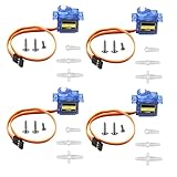
- SG90 9G micro digital servo motor made from high-quality plastic and featuring a gear medium, this servo motor is durable and reliable, ensuring that it provides long-lasting performance even after multiple uses
- SG90 9g micro digital servo motor servo motor can operate within a voltage range of 4.2-6V, making it compatible with a wide range of power sources
- SG90 9G micro servo motor with a torque of 1.6KG/CM (at 4.8V) and a response speed of 0.3s/60 degrees, this servo motor provides high performance and fast response times
- SG90 9G servo motor features a small size and lightweight design, making it ideal for use in a wide range of electronic projects
- This sg90 servo motor is suitable for use in a wide range of electronic diy projects, including 450 fixed-wing and helicopter models, as well as other robotics applications
Typical parts
- NE555 timer IC
- Potentiometer suitable for manual adjustment
- Fixed resistors and timing capacitors selected for the chosen schematic
- Breadboard or perfboard
- Three-wire servo connector or the servo’s lead
- Regulated supply appropriate for both the timer circuit and servo
- Power switch, hookup wire and a supply-decoupling capacitor
Do not copy component values from an unverified version of the circuit. There are several 555 servo-tester topologies, and the indexed text of the Make project does not provide a complete, reliable bill of materials. Use the actual schematic and transcribe every value, or calculate and verify an independent design before building it.
Outdated Drivers Are Slowing You Down
One free scan finds every outdated or missing driver and matches the right update for your exact hardware.Free scan · exact hardware matchWindows Errors? Fix Them Before They Spread
Repair common Windows errors and clear accumulated junk for a smoother, more stable PC - no reinstall needed.Free scan · no reinstall555 pin functions
| 555 pin | Function | General connection |
|---|---|---|
| 1 | Ground | Controller ground |
| 8 | Positive supply | Regulated positive rail within the selected 555’s rating |
| 4 | Reset | Normally held high when reset is unused |
| 3 | Output | Servo signal input, provided logic levels are compatible |
| 2, 6 and 7 | Trigger, threshold and discharge timing functions | Connect according to the verified circuit topology |
Place the supply-bypass capacitor close to the IC’s supply pins. Keep the signal and ground connections short and secure. The potentiometer must be wired exactly as shown in the selected design; different circuits use it in different parts of the timing network.
Build on a breadboard first
- Confirm the NE555 pin orientation and the chosen schematic.
- Assemble the timer and timing network without attaching the servo.
- Check for shorts and verify supply polarity.
- Power the controller and confirm that it oscillates. An oscilloscope or logic analyser is the best way to check the period and pulse width.
- Set the potentiometer near its middle position.
- Connect the servo only after the controller supply and signal have been checked.
- Test the unloaded servo slowly before transferring the circuit to perfboard or a permanent enclosure.
This approach is inexpensive and educational, but component tolerances, supply noise and potentiometer behaviour can affect calibration. The knob may not provide a perfectly linear relationship with shaft angle.
Rank #4

- SG90 9G digital Servo - Miuzei 9g servo motor for remote control helicopters, micro robot, robot arm and boats. Fit for ALL kinds of R/C car and also make electronics DIY compatible with Arduino, Raspberry Pi.
- Mini Servo - small servo motor compatible with JR and Futaba interface. Micro servo running speed (at no load) : 0.09 sec/60° (4.8V) 0.08 sec/60°(6V). Running angle: 180 degree.
- Micro Servo Motor - Stall Torque (4.8V): 19.6 oz /in (1.4kg/cm). Dead band width: 5 usec. Operating Voltage: 4.8V-6.0V.
- Application Fields -Servos used for drone, DIY project, RC crawler, helicopterfixed-wing, helicopter, KT, glider, small robot, robotic arm and other models.
- Note - Starting current of the analog servo motor should be over 1A and servo sg90 are analog servos need to continuously provide a PMW signal, then it will be work normally.
Option 2: Buy a hardware servo tester
A dedicated tester is the better choice when you want a knob or switch interface without designing a timing circuit. It avoids most breadboard troubleshooting and is generally quicker to deploy.
One documented example is SparkFun’s Continuous Rotation Servo Trigger, product WIG-13872. It provides code-free control for a continuous-rotation hobby servo, with trimpots for speed and direction and a switch for reversing direction. Its listed price was observed at $17.50 in 2026; price, stock and product status can change, so verify the official product page before buying.
The Tool Desk
Outbyte PC Repair FREERepair Windows errors before they cause bigger problemsFix Now →Outbyte Driver Updater FREEFix the driver behind crashes, sound loss and screen glitchesFind Drivers →Compatibility warning: this particular product is intended for continuous-rotation servos. It is not automatically the right controller for a normal 180-degree positional servo. For positional control, choose a tester explicitly labelled for standard servos and check its voltage and pulse-range specifications.
Best Value
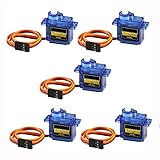
- 100% NEW brand,high quality. Stall Torque (4.8V): 17.5oz /in (1kg/cm); Operating voltage: 3.0V~ 6V; Temperature range: -30 to +60; Dead band width: 7usec
- Mini servo SG90 is tiny and lightweight with high output power
- SG90 servo motor compatible with the project like Robot Arm/ Robot hand/ control the servo with potentiometer/ multi servo control
- The SG90 has 3 wire interfaces in which the connections should be made as follows: Red wire-5V, Brown Wire-Ground, Yellow wire-digital pin 9
- SG90 9G micro servo motor for remote control helicopters, micro robot, robot arm and boats
Wiring and power
The generic wiring model is:
| Servo function | Connect to |
|---|---|
| Ground | Controller ground and supply negative |
| Positive supply | Supply voltage specified for the servo |
| Signal | 555 output or compatible servo-controller output |
The controller and servo must share a common ground. Do not assume that a red lead can be connected to 5 V, and do not rely on wire colour alone. Verify the servo’s rated voltage and connector pinout.
The signal generator supplies timing, not the servo’s operating current. A servo can draw considerably more current while starting, lifting a load or stalled against a stop. Avoid powering a high-current servo through a weak USB port or a small logic-board regulator. Use a separate regulated servo supply when necessary, connect its ground to the controller ground, and add decoupling close to the servo and controller. Arduino’s technical guidance on servos and motor power explains why motor loads and logic supplies should be treated separately.
Safe first test and calibration
- Identify the servo type and confirm its rated supply voltage.
- Verify the connector’s power, ground and signal functions.
- Build or buy the controller.
- Power the controller without the servo attached and confirm its expected voltage.
- Turn the control knob near its middle position.
- Disconnect power before attaching the servo.
- Reapply power with the mechanism unloaded and clear of pinch points.
- Turn the knob slowly.
- Stop immediately if the servo chatters violently, overheats, stalls or reaches a hard mechanical stop.
- Mark the usable knob range and only then attach the linkage or construction mechanism.
For a positional servo, find the practical end points rather than assuming the full electrical range is safe. For a continuous-rotation servo, adjust the neutral setting until the shaft stops, then mark useful forward and reverse speed positions.
Troubleshooting
| Symptom | Likely causes | What to check |
|---|---|---|
| No movement | Wrong pinout, no common ground, no signal or incorrect supply | Verify polarity, connector orientation, voltage, ground continuity and timer output |
| Jitter | Noisy or weak supply, unstable timing, loose ground or mechanical binding | Add decoupling, improve wiring, use a stronger regulated supply and remove the load |
| Moves only one direction | Restricted pulse range, incorrect potentiometer wiring or wrong servo type | Identify the servo and recalibrate with conservative pulse limits |
| Buzzes continuously | Unstable command, linkage force or a hard mechanical stop | Reduce the command range, free the linkage and check the supply |
| Overheats | Wrong voltage, reversed power, stall, excessive load or invalid pulse width | Disconnect immediately and verify every rating and mechanical limit |
| Works unloaded but fails under load | Supply voltage droop or inadequate current capacity | Use a properly rated supply and reassess the mechanical load |
A small holding sound can be normal when a positional servo maintains a loaded position. Persistent loud buzzing is a warning that the command is unstable or the mechanism is forcing the servo against resistance.
When programming becomes the better option
A 555 circuit or manual tester is ideal for one-knob control. Use a microcontroller when the servo must respond to sensors, buttons, schedules, serial commands or network input; perform repeatable sequences; control several servos; detect limits; or follow acceleration and timing profiles. A PCA9685-style multi-channel board can provide centralised servo timing, but it is not automatically a no-programming, knob-based solution and often requires a host controller or configuration method.
Quick Recap
Which approach should you choose?
- Build the 555 circuit if you want to learn electronics, need one manual control, and want a genuinely non-programmable design.
- Buy a compatible servo tester if quick setup, compact packaging and predictable operation matter more than building the circuit.
- Use a microcontroller if the project needs automation, multiple motion profiles, sensors or future expansion.
Product prices and availability are accurate as of the date/time indicated and are subject to change. Any price and availability information displayed on Amazon at the time of purchase will apply.