The Tool Desk
Outbyte PC Repair FREEClear out junk files and repair common Windows errorsFree Scan →Outbyte Driver Updater FREEScan for outdated or missing drivers - takes under a minuteDriver Scan →A relay is faulty only after you have checked that it receives the correct command and that its contacts fail to switch the circuit as specified. A click alone does not prove the contacts are good, and a relay that appears bad may instead have a blown fuse, poor connection, missing control signal, wiring fault, or failed load. The checks below apply to automotive low-voltage circuits; for mains-powered or industrial equipment, follow its service procedure and use appropriately trained personnel.
Start by identifying the circuit and symptom
Note what has stopped working, whether the fault is constant or intermittent, and the conditions in which it occurs. Use the vehicle wiring diagram or service information to identify the relay, its coil control circuit, switched contacts, fuse protection, and connected load. A relay that looks similar is not necessarily interchangeable: verify its pin diagram and ratings before swapping it.
Inspect the relay, socket, fuse, and wiring
Make the vehicle and circuit safe according to the service procedure before inspecting or testing. Look for heat damage, corrosion, loose terminals, water intrusion, damaged wiring, and a blown relevant fuse. A poor socket connection, bad ground, failed load, or absent command can produce symptoms that resemble a bad relay. Do not bridge terminals by guesswork; first establish their functions and understand the downstream circuit.
Check whether the relay receives its control signal
With the circuit commanded on, measure voltage across the coil terminals identified by the relay diagram. Compare the result with the vehicle service information and the exact relay datasheet. TE Connectivity’s relay diagnosis guidance checks whether coil voltage meets the relay’s specified minimum before assessing armature movement.
#1 Best Overall

- Integrated Diode: Each relay includes a built-in diode that suppresses induced voltage during switching, safeguarding your electrical components from potential damage.
- Small size/Low power consumption/High contact voltage/ High sensitivity.
- Contact Material: Ag Alloy / Contact Resistance: ≤ 100MΩ.
- Minimum operating voltage 8V, corresponding minimum operating current is 100mA; Standard operating voltage 12V, corresponding standard operating current is 150mA.
- Life Expectancy Electrical: 100,000 Operation, Life Expectancy Mechanical: 10,000,000 Operation.
- Expected coil voltage is absent or too low: investigate the control signal, wiring, grounds, and circuit protection upstream. This reading does not establish that the relay itself has failed.
- The relay clicks: that suggests possible armature movement, but it does not show that the contacts can carry current correctly. TE treats coil operation and contact performance as separate checks.
- Expected coil voltage is present but the relay does not operate: the relay may be faulty, but confirm the measurement points and compare against the correct specifications before condemning it.
Measure coil resistance only with the relay isolated
Remove the relay and isolate it from circuit power before using an ohmmeter or continuity mode. Fluke cautions: “Avoid testing powered circuits in continuity or resistance mode — this can damage the meter.” Its automotive continuity guidance also says to disconnect battery power or isolate the circuit before continuity testing.
Identify the coil terminals from the relay’s diagram and measure across them. Compare the reading with the specification for that exact relay; there is no universal coil-resistance pass/fail value because designs differ and resistance varies with temperature. An open reading can indicate an open coil. If a value appears out of specification, repeat the measurement under the manufacturer’s prescribed conditions and consult its procedure. TE’s Power Relay F datasheet illustrates model-specific coil configurations and values; it is not a general standard for other relays.
Rank #2
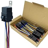
- Never go beyond its capabilities. Try to stay 10 to 15% below what the rate is for
- 12-volt 5-prong (SPDT) relay. Excellent water-repellent and dustproof ability, but do not use it in water
- Be careful when inserting the relay into the socket. If you force it, you will bend the female connectors
- Primary leads use 12 a.w.g tinned copper wire. Coil leads use 16 a.w.g
- Nominal Coil Voltage: 12 V DC; Coil Power: 1.8 W; Coil Resistance: 80 Ω; Must Operate Voltage: 6~8 V DC; Must Release Voltage: 0.6~3.6 V DC; Maximum Applied Voltage: 15.6 V DC
Check contact performance under appropriate conditions
A continuity beep or an unloaded resistance check is not conclusive for a used power relay. Contacts can be affected by pitting and arc residue, so a contact path that appears continuous at a low test level may not perform properly under load. TE recommends functional contact monitoring at voltage and current appropriate to the relay.
TE’s September 2020 guidance gives roughly 12 V and 100 mA or 500 mA as typical levels for certain used-relay functional checks, but these are general guidance, not a universal test prescription. Use the exact relay datasheet and vehicle service procedure to determine suitable conditions; do not improvise a test load or expose yourself to hazardous energy. Unreliable switching or intermittent operation under an appropriate test makes the relay suspect.
Rank #3

- High switching capability: Normally open 40A/14V DC and normally close 30A/14V DC. Suitable for Nilight LED light bar wiring harness kit
- Premium quality: Durable relay and harness socket with 5 wires; Made by high-grade materials to ensure superior quality and long lifespan
- Male-female slot design: Unique male-female slot design, easy to connect the relay with harness socket, clean and neat after installation
- Easy wiring: The relay sockets come with different colors for loads/accessories, simple and convenient wiring
- Package include: 5 x relay and 5 x relay socket with wires.Fit type: Universal fit
If the relay passes, trace the rest of the circuit
Check the control and load paths separately rather than replacing a relay based on symptoms alone. Voltage-drop testing under operating load can reveal excessive resistance in wiring, grounds, connectors, or switched paths that limits voltage reaching the relay or its load. Follow the vehicle-specific procedure; Fluke explains this approach in its automotive voltage-drop guidance.
- Confirm the command reaches the relay coil when the circuit is requested.
- Check relevant supply and ground paths under operating load.
- Inspect connectors and the socket for resistance, looseness, or heat damage.
- Verify the load itself and its wiring before concluding the relay is responsible.
Choose a replacement by specification, not appearance
Use vehicle application data or the original equipment number, then confirm compatibility against the exact replacement datasheet. Check coil voltage and configuration, contact arrangement, pinout, any suppression diode or resistor requirements, and switching or current ratings. Physical fit alone does not establish electrical compatibility; the TE automotive relay datasheet demonstrates that these details are product-specific.
Quick Recap
Best Value

- Upgraded Version - Automotive relays built in fuse socket included 30A blade fuse with heavy duty 14AWG wires for main contact. no need of a separate fuse holder, saving space and money. 4-Pin SPST (Single Pole Single Throw) Relay.
- Mounting Design Feature - The interlocking mounting design of unique male and female slot on each socket edge, connect relays together and manage cables easily, offering clean and neat installation.
- Easy Wiring - The relay sockets come with color-labeled wires for load/accessories convenient wiring. Black - Ground (85), Red - VDC (30), White - Trigger (86), Blue - Output N/O (87)
- Wide Application - Widely used in car keys power control, over-load protection, trunk release, polarity change, power door lock/actuator control, change a low current output to high current, add ignition/accessory outputs, control motors/other electronics etc.
- Set includes 5 relays, 5 relay harnesses, and 5 30A blade fuses.
Rank #4

- 【12V 40A PEAK CAPACITY】Rated for 12V DC systems with a 40A max peak switching current (1.8W coil power, 80Ω resistance). Always keep your continuous loads 10% to 15% below the rated value to ensure maximum electrical safety and relay longevity
- 【PREMIUM AgSnO2 CONTACTS】This 4-pin SPST automotive relay features premium Silver Tin Oxide (AgSnO2) contacts for maximum resistance to arc erosion and contact welding. Rated for a 27V DC max switching voltage, it guarantees extended operational durability and reliable switching performance under heavy loads
- 【PLEASE NOTE SIZE】Check the product dimensions carefully (2.44 x 1.77 x 1.38 inches, excluding wires) before purchasing to ensure a proper fit for your space/application
- 【14AWG TINNED COPPER】Unlike inferior aluminum wires, our premium tinned copper design offers superior conductivity and is far more corrosion-resistant than standard bare copper. Specs: 16AWG (85/86) for control, and 14AWG (30/87) for reliable standard power output
- 【WEATHER-RESISTANT】Engineered with a tight housing to protect internal contacts from moisture, dust, and debris. Ideal for under-hood installations and outdoor applications. Please note: This unit is splash-proof only; do not submerge completely in water
Product prices and availability are accurate as of the date/time indicated and are subject to change. Any price and availability information displayed on Amazon at the time of purchase will apply.