Some links on this page are affiliate links: if you buy through them we may earn a commission, at no extra cost to you.
There is no universal vacuum-cleaner motor wiring diagram or color code. Many corded household and commercial vacuums use a series-wound universal motor, but the complete circuit may also include a switch, thermal protector, circuit breaker, noise-suppression components, or electronic speed control. Cordless vacuums may use brushed DC or brushless motors that require a battery and controller.
Use the exact wiring diagram for the vacuum’s model, voltage, motor part number, and control-board revision. Never identify terminals by wire color alone, connect an unidentified motor directly to household power, or bypass a thermal protector, fuse, breaker, switch, or controller.
As an Amazon Associate I earn from qualifying purchases.
Quick wins for a faster PC:
Repair Windows errors before they cause bigger problemsFix Now →Fix the driver behind crashes, sound loss and screen glitchesFind Drivers →Clear out junk files and repair common Windows errorsFree Scan →Safety first
Motor wiring involves mains voltage, stored electrical energy, hot components, and rapidly rotating parts. The normal diagnostic workflow should be de-energized inspection and testing—not trial-and-error live testing.
- Unplug a corded vacuum before opening it. Remove the battery or disconnect the battery pack from a cordless model.
- Do not rely on the on/off switch as isolation. For hard-wired equipment or commercial installations, isolate the relevant circuit and follow applicable lockout procedures.
- Verify the absence of voltage with an appropriately rated test instrument. A non-contact voltage pen or indicator lamp is not sufficient proof that an appliance is dead.
- Allow capacitors and electronic components to discharge as specified by the service documentation.
- Keep the appliance away from water, combustible debris, and loose clothing while it is open.
- Do not perform a live mains test unless you are qualified and have suitable guarding, current protection, isolation, and test equipment.
OSHA requires exposed live parts to be de-energized when feasible and the absence of voltage to be verified with test equipment. Its guidance also addresses backfeed, stored energy, and other sources that can leave equipment energized: OSHA electrical safety requirements, OSHA lockout/tagout requirements, and OSHA verification guidance.
#1 Best Overall

- 8.0 amps, 120 Volts
- 2 Stage; Peripheral Discharge
- 84.3 CFM
- 5.7" Diameter Bypass Vacuum Motors/Blowers
- 6 15/16" Overall Height
Identify the motor type before tracing wires
“Vacuum motor” can describe several electrically different assemblies. Do not apply the wiring for one type to another.
| Motor or assembly | Typical supply | Wiring implication |
|---|---|---|
| Corded universal suction motor | AC mains | Usually a series field-and-armature circuit; may be controlled by a triac or another electronic module. |
| Brushed DC motor | Battery or low-voltage DC supply | Polarity, battery protection, and a control board may matter. It must not automatically be connected to 120 or 230 V AC. |
| Brushless or electronically commutated motor | Controlled DC or AC/DC system | Usually requires a dedicated controller and may have phase, sensor, or communication wires. |
| Floor-brush or agitator motor | Separate appliance branch | May have its own switch, belt-load protection, thermal switch, interlock, or controller. |
| Central-vacuum or commercial multi-motor equipment | Model-dependent AC supply | May use multiple motors, relays, contactors, breakers, and separate 120 V or 220–240 V arrangements. |
Many corded vacuum suction motors are universal motors. Toshiba describes this type of motor and triac phase control for adjusting power in corded vacuum applications: Toshiba’s vacuum-motor application note.
What’s actually slowing this PC down?
Pick the symptom - the matching free tool is one click away.
The common corded universal-motor circuit
A universal motor has stationary field windings and a rotating armature connected through carbon brushes. In the common series arrangement, the field winding, armature, and return field section carry the same current.
Line/hot ── switch ── thermal protector ── field winding ── brush
                                              │
                                         armature
                                              │
                                      brush ── field/return ── neutral

Protective earth ───────────────────────────── metal chassis
This is a conceptual explanation of motor topology, not a connection instruction. The physical order varies. Some complete motor assemblies internally join the field and brush circuits and expose only two power terminals. Others expose separate field, brush, thermal-protector, tachometer, or control terminals.
A practical simplified appliance circuit may look like this:
Line/hot ── main switch ── protector ── motor ── neutral
Ground ─────────────────────────────── metal chassis
Some models instead place an electronic speed-control board between the switch and motor:
Crashes, No Sound, or Screen Glitches?
Random freezes, missing sound and display glitches usually trace back to one bad driver. Find and replace yours safely.Free scan · under a minutePC Slower Than It Used to Be?
A free scan shows the junk files, broken settings and background clutter dragging Windows down - then fixes them in one click.Free scan · Windows 10 & 11Rank #2

- Direct Replacement for Multiple Models:Compatible with popular vacuum models including 56207802, 62515-00-2,44903A, 380001, 14800, 1902,330,CAV26,cetral vac CV40-D, 296439 and more. Designed for seamless integration as a replacement motor for central vacuum systems and commercial/residential vacuum cleaners.
- Powerful 2-Stage Motor for Deep Cleaning:Equipped with a high-efficiency two-stage design, this motor delivers strong, stable suction for deep cleaning across different surfaces. Ideal for homes, offices, and workshops.
- Quiet and Energy-Efficient 116336-01 Motor: Designed for quieter environments, this motor runs smoothly with reduced noise and optimized power usage, making it a smart choice for energy-conscious households.
- Includes Motor Gasket 566 & Extra Carbon Brushes: Includes a precision-fit 5.7" motor gasket and two sets of carbon brushes—one pre-installed and one extra—for extended durability. Specifically designed for 116336-01 and 116336-00, this motor ensures reliable performance and reduced maintenance needs.
- Simple Installation, Reliable Fit: Direct replacement for 116336-01, 116336-00 vacuum motors. Designed for a secure and stable fit in a variety of vacuum units without the need for complicated modifications.
Line ── switch ── speed-control board ── universal motor ── neutral
Ground ───────────────────────────────────────────── chassis
Triac control changes the power supplied to a universal motor. Bypassing the original controller can cause excessive speed, high inrush current, brush arcing, overheating, or immediate motor failure.
Commercial vacuum documentation illustrates the same principle: the motor is not treated as an isolated two-wire component but appears alongside switches, breakers, brushes, and cord assemblies. See the Clarke service documentation.
What the wires and terminals may represent
Wire colors can provide clues, but they do not establish terminal identity. Depending on the country, manufacturer, and location in the appliance, black, brown, red, white, blue, or other colors may be used for supply, field, brush, thermal, sensor, or control wiring. Internal motor leads may follow no obvious appliance-cord convention.
Green or green/yellow commonly identifies protective earth in many systems, but some plastic-bodied appliances are double-insulated and have no equipment-grounding conductor. Never add or remove a ground connection based only on appearance. Reproduce the original construction and follow the manufacturer’s instructions.
North American cord conventions such as black for line and white for neutral do not identify every internal motor lead. Read the schematic by terminal marking and circuit function, not color alone.
Check the appliance nameplate for:
- Rated voltage and frequency.
- Current or wattage.
- Manufacturer and complete model or type number.
- Motor part number, if shown.
- Double-insulation markings or grounding requirements.
Appliance nameplates are intended to identify electrical ratings; OSHA’s electrical provisions discuss voltage and amperage or wattage identification: OSHA appliance requirements.
Rank #3
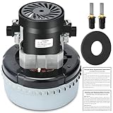
- Compatible with Multiple Vacuum Models:This vacuum motor fits a wide range of models, including 56207802, 44903A, 380001, 296439, 14800, 1902,330,cav26,62515-00-2,cetral vac CV40-D and more. It’s a perfect replacement for central vacuum installation parts and vacuum cleaner motors, ensuring seamless integration.
- High Efficiency & Strong Suction Power:Designed as a high-performance vacuum motor, this 2-stage brushed motor vacuum delivers powerful suction and deep cleaning capabilities, making it ideal for both residential and commercial use.
- Low Noise & Energy Efficient Operation:This vacuum cleaner motor operates quietly and efficiently, reducing noise disruption and energy consumption. It’s perfect for environments where quiet operation and energy savings are essential.
- Includes Motor Gasket 566 & Extra Carbon Brushes:Comes with a 5.7-inch Motor Gasket (#566) for a secure fit and enhanced performance. The motor itself includes a pair of carbon brushes, and an additional pair is included for extended use, ensuring long-lasting durability.
- Easy to Install & Versatile Use:Designed for hassle-free installation, this vacuum motor is a direct replacement for 116336-01 and 116336-00. It’s versatile and suitable for various applications, including central vacuum installation parts.
How to find the correct wiring diagram
- Record the complete identity. Write down the manufacturer, model, type or revision number, voltage, regional version, serial-number range, and motor part number.
- Photograph the assembly. Take clear photographs before removing a connector, including both ends of each wire and the route through clips and strain reliefs.
- Label destinations. Mark a wire as “switch output to thermal protector,” for example, rather than merely “red wire.”
- Search for the manufacturer’s documentation. Use terms such as “service manual,” “wiring diagram,” “schematic,” “electrical diagram,” “parts breakdown,” and “motor replacement procedure.”
- Match every detail. Confirm the diagram covers the same model, voltage, motor part number, switch arrangement, and control-board revision.
- Trace before reconnecting. If no appliance diagram exists, use the motor manufacturer’s terminal information and trace the surrounding harness. Do not discover unknown terminals by applying power.
Commercial parts diagrams often list separate motors, breakers, switches, brush components, and power cords for a particular model. A Clarke Clean Track 12 diagram is one example: model-specific Clarke parts documentation.
Safe, de-energized diagnostic sequence
1. Inspect before measuring
Look for burned or discolored terminals, melted insulation, loose crimps, carbon tracking, damaged strain reliefs, pinched wires, missing insulating sleeves, broken brush leads, damaged grounding conductors, and terminals that could contact the housing.
Do these 3 things before closing this tab:
1Clear out junk files and repair common Windows errors2Scan for outdated or missing drivers - takes under a minute3Repair Windows errors before they cause bigger problemsAlso check for blocked filters or hoses, motor contamination, seized bearings, and restricted cooling airflow. Many vacuum motors depend on the fan and airflow through the housing for cooling.
Do not reuse an overheated push-on terminal merely because it still fits. Replace damaged connectors with parts rated for the circuit’s current and temperature.
2. Check the cord and switch
With the appliance disconnected, use a multimeter to check each cord conductor end-to-end and operate the switch while measuring the appropriate terminals. Compare the result with the schematic. Check the conductor for intermittent operation by gently flexing the cord only during the de-energized test.
3. Check the thermal protector correctly
A thermal protector is often placed in series and may be normally closed when cool, but its exact state, reset behavior, and location must be confirmed from the service information. It may be embedded in the motor, attached to a winding, mounted in the housing, or be a one-shot thermal fuse.
Rank #4

- Description:9.5 AMP, Single Speed, Comes With Fan
- Works With: Eureka 1400 Eureka 1401 Eureka 1402 Eureka 1403 Eureka 1404 Eureka 1405 Eureka 1406 Eureka 1407 Eureka 1408 Eureka 1409 Eureka 1410 Eureka 1411 Eureka 1412 Eureka 1413 Eureka 1414 Eureka 1420 Eureka 1421 Eureka 1415 Eureka 1416 Eureka 1417 Eureka 1418 Eureka 1418 Eureka 1419 Eureka 1422 Eureka 1423 Eureka 1424 Eureka 1425 Eureka 1426 Eureka 1427 Eureka 1428 Eureka 1429 Eureka 1430 Eureka 1431 Eureka 1432 Eureka 1435 Eureka 1436 Eureka 1437 Eureka 1438 Eureka 1439 Eureka 1440
- Works With: Eureka 1441 Eureka 1442 Eureka 1443 Eureka 1444 Eureka 1446 Eureka 1447 Eureka 1448 Eureka 1450 Eureka 1452 Eureka 1453 Eureka 1454 Eureka 1455 Eureka 1455 Eureka 1456 Eureka 1457 Eureka 1458 Eureka 1459 Eureka 1462 Eureka 1463 Eureka 1466 Eureka 1469 Eureka 1470 Eureka 1471 Eureka 1473 Eureka 1485 Eureka 1486 Eureka 1489 Eureka 1490 Eureka 1495
- Works With: Sanitaire SC678 Sanitaire SC688 Sanitaire SC888 Sanitaire SC883 Sanitaire SC684 Sanitaire SC886 Sanitaire SC887 Sanitaire SC899 Sanitaire SC681 Sanitaire SC882 Sanitaire SC679
Never short it out permanently or replace it with a higher-rated device. If it opens repeatedly, investigate blocked airflow, dirty filters, bearing friction, brush wear, incorrect voltage, a wrong replacement motor, or inadequate cooling.
4. Check the motor circuit
Measure the field-and-brush circuit only after you understand the terminal layout. A resistance or continuity reading can identify an open circuit, but it cannot prove that the motor is serviceable. A motor may show continuity while suffering from shorted turns, a damaged commutator, worn brushes, bearing friction, intermittent winding faults, or insulation breakdown.
Do not use resistance readings to guess which unknown terminals should receive mains voltage. Similar readings can occur across different combinations of field and brush connections.
5. Consider insulation testing carefully
An insulation-resistance tester may be appropriate for an isolated motor assembly, but its test voltage can damage electronic controls, suppression capacitors, sensors, or circuit boards. Disconnect components only as directed by the service manual or motor manufacturer, and use the specified test voltage and pass value.
Free tools Windows power users keep installed
One-click scans. No signup required.
Symptoms and likely wiring or motor faults
| Symptom | Possible causes | Safe next step |
|---|---|---|
| Motor is completely dead | Open cord, switch, thermal protector, brush, field winding, armature, neutral, or control board. | Trace the complete circuit against the schematic; do not bridge unknown components. |
| Breaker trips immediately | Shorted wiring, failed suppression component, shorted winding, seized motor, wrong motor, or incorrect connection. | Stop powered testing and inspect the circuit de-energized. |
| Motor hums but does not run | Open brush circuit, worn brushes, failed controller, or mechanical seizure. | Inspect brushes and bearings and follow the model’s service procedure. |
| Heavy or uneven sparking | Worn brushes, damaged commutator, armature fault, poor brush seating, or overload. | Remove the motor from service and have the motor assembly inspected or replaced. |
| Motor overheats | Blocked filter or hose, bearing friction, worn brushes, wrong voltage, or failed thermal protection. | Correct the airflow or mechanical fault before replacing any protector. |
| Runs only when wires are moved | Loose crimp, broken conductor, cracked solder joint, or worn switch contact. | Replace the faulty connection; do not leave a twisted, taped, or temporary repair. |
| Runs at excessive speed | Bypassed speed controller, wrong motor, incorrect field/armature connection, or controller failure. | Disconnect power and restore the specified circuit. |
| Shock sensation or ground-fault trip | Missing ground, damaged insulation, contamination, or winding-to-frame fault. | Remove the appliance from service and obtain insulation and grounding checks. |
| Works briefly, then stops | Thermal protector opening because of overload, blocked airflow, overheating electronics, or mechanical friction. | Find and correct the cause rather than repeatedly resetting or bypassing protection. |
| Brush motor works but suction motor does not | Separate switch, breaker, motor, or wiring branch. | Use the model’s multi-circuit schematic; the working brush circuit does not identify the suction-motor fault. |
Commercial carpet-cleaning equipment can have separate suction, brush, pump, switch, and breaker branches. See this example of a multi-branch wiring diagram: Windsor vacuum documentation.
Replacement-motor compatibility checklist
A motor that fits physically is not necessarily electrically compatible. Before purchasing or installing a replacement, match:
Best Value

- Compatible With: 836099 vacuum motor is designed to be compatible with proteam super coach, proteam 107303, provac Backpack, pro6 and pro10. Part number: 834036, 836099
- Quality Construction: Our 834036 836099 proteam vacuum motor is made with quality components available, featuring quality tested items with unsurpassed reliability
- Replacement Solution: If your proteam super coach pro 10 and super coach pro 6 vacuum shuts off suddenly, try replacing the 834036 836099 motor to get your vacuum working again
- Customer Support: We have a professional team available to assist you with any questions or concerns about this vacuum motor replacement
- Parametric Specifications: 834036, 836099 vacuum motor operates at 120V 60Hz 1400W for reliable and consistent performance
- Voltage, frequency, current, and wattage.
- Motor part number and appliance model.
- Mounting dimensions and fasteners.
- Fan or impeller arrangement, airflow direction, and cooling requirements.
- Terminal configuration and connector type.
- Internal or external thermal protection.
- Brush type and brush-holder arrangement.
- Compatibility with the original speed-control board.
- Insulation, grounding, and applicable certification requirements.
Do not assume a 120 V and 220–240 V motor are interchangeable. A 120 V motor connected to 230 V can fail violently and create a fire hazard; a 230 V motor on 120 V may fail to start or draw abnormal current. Commercial documentation commonly lists separate voltage-specific motors and protection components, as shown in this Clarke schematic.
Special cases
Double-insulated appliances
A plastic-bodied vacuum may be designed with reinforced or double insulation rather than an equipment ground. Preserve that design. Do not connect a green or green/yellow conductor to a motor power terminal, and do not add a chassis ground without knowing the appliance’s construction.
Recommended Free Tools
Cordless and brushless vacuums
Cordless units may contain lithium-ion battery packs, battery-management systems, Hall sensors, multiple motor phases, proprietary connectors, and electronic commutation. Do not apply mains voltage to a cordless motor, bypass battery protection, or connect a brushless motor directly to a battery unless the manufacturer specifies the complete arrangement.
Separate floor-brush motors
Upright and commercial machines may use independent suction and agitator motors. The floor-brush circuit can include a separate switch, belt-load protector, upright-position interlock, or thermal device. Its wiring cannot be used to infer the suction-motor wiring.
Temporary direct-power tests
Touching unidentified wires to a battery or wall outlet is not a reliable diagnostic method. It can bypass protective devices, expose a high-speed fan, cause dangerous arcing, and destroy an incorrect motor or controller. If a powered test is genuinely necessary, it belongs in a controlled qualified-service procedure.
When to stop the repair
Hand the appliance to a qualified technician when it is hard-wired, uses a control board or brushless motor, shows burned wiring or insulation damage, has a ground-fault symptom, requires live testing, or has no obtainable model-specific schematic. The same applies when the replacement motor does not exactly match the original voltage, part number, protection, terminals, mounting, and airflow requirements.
The Tool Desk
Outbyte Driver Updater FREEScan for outdated or missing drivers - takes under a minuteDriver Scan →Outbyte PC Repair FREERepair Windows errors before they cause bigger problemsFix Now →For a construction or commercial setting, use extra caution: equipment may have higher duty cycles, multiple motors, separate breakers, contactors, or wet-environment exposure. A generic household wiring diagram is not an acceptable substitute for the equipment’s service documentation.
Quick Recap
Product prices and availability are accurate as of the date/time indicated and are subject to change. Any price and availability information displayed on Amazon at the time of purchase will apply.

