Quick wins for a faster PC:
Repair Windows errors before they cause bigger problemsFix Now →Fix the driver behind crashes, sound loss and screen glitchesFind Drivers →Clear out junk files and repair common Windows errorsFree Scan →Four primary wires and two secondary wires often indicate a dual-primary, single-secondary transformer—but wire count alone does not prove the connection. A common 115/230 V transformer uses two equal primary windings: connect them in parallel for the lower rated input voltage or in series for the higher rated input voltage. The two secondary wires are normally the terminals of one AC output winding.
Do not connect an unidentified transformer to mains power based only on its wire count or insulation colors. Use the exact nameplate, terminal markings, manufacturer diagram, and datasheet. If the input voltage, winding arrangement, phasing, or insulation condition is unknown, stop and have a qualified electrician or transformer technician identify it.
As an Amazon Associate I earn from qualifying purchases.
What four primary wires usually mean
In many control and low-voltage transformers, four primary leads represent two separate primary windings. Each winding has two ends. The manufacturer may design those windings for either:
- Series operation on the higher input voltage; or
- Parallel operation on the lower input voltage.
For example, a transformer marked 115/230 V primary, 12 V secondary may use its two 115 V primary windings in parallel on a 115/120 V supply and in series on a 230/240 V supply. The secondary remains a nominal 12 V AC winding, although its measured voltage can vary with load and regulation.
#1 Best Overall

- True 1600W Continuous Pure Sine Wave Power — 24-Hour Full-Load Tested: HYTED 220V to 110V converter converts 220-250V down to a stable 120V pure sine wave, Suitable for any American appliances with 110-120V and power ranging from 0-1600 watts. No Load-Type Restrictions — Heating, Motor, Electronic, Sensitive & Mixed Loads
- International Power Adapters for Europe, UK & Italy: HYTED includes a Type E/F power cord for outlets in France, Germany, Spain, and much of Europe, plus 3 international power adapters: Type C for compatible outlets in Italy and Europe, Type G for the UK and Ireland, and Type I for Australia and China. Designed for U.S. appliances traveling to 220–250V countries, with plug options suitable for use in over 160 countries.
- Advanced Safety & 35A Startup Inrush Current (surge) Control: HYTED's design takes into account the high startup inrush currents of motor-driven and other high-inrush appliances, which may briefly draw 2–3 times their normal operating current. Its intelligent startup current control limits inrush current to approximately 35A at 120V, helping protect the converter while allowing compatible appliances to start normally. Additional protections include overheating, overload, over-current, surge, and short circuit. CE certified and UL safety tested.
- Intelligent Protection: Automatically cuts off power and flashes the indicator light when detecting abnormal conditions, such as power surges, short circuits, or extreme input voltage fluctuations. Simply restart once the issue is resolved. With over 50,000 units sold and no confirmed cases of connected appliance damage, HYTED is designed to protect your appliances even in regions with unstable power grids.
- 100% Satisfaction: The HYTED 1600Watts 220V to 110V Converter International Power Adapter Combo is backed by a reliable 24-month warranty and supported by a team of friendly customer service professionals. For any inquiries, please email us, and our technical representative will respond within 12 hours.
However, four leads can also represent a tapped winding, two windings that must remain separate, a special-purpose transformer, or a nonstandard terminal arrangement. Four flying leads do not identify which wires belong together, which ends are phased alike, or what voltage the transformer can withstand.
Manufacturer terminal numbers and colors are not universal. For example, Schneider Electric documents a common H1–H4 arrangement in which H2–H3 are joined for the series, high-voltage connection, while H1–H3 and H2–H4 are joined for the parallel, low-voltage connection. That arrangement applies only when the transformer uses the same terminal convention and phasing shown in the manufacturer’s diagram.
Read the nameplate before wiring
Find and record the following information before making any connection:
- Manufacturer and exact part number;
- Primary voltage or voltage combinations, such as
115/230 V,120/240 V, or2 × 115 V; - Secondary voltage and rated current;
- VA or kVA rating;
- Rated frequency, such as 50 Hz, 60 Hz, or 50/60 Hz;
- Terminal labels, such as H1, H2, H3, H4, X1, and X2;
- A printed series/parallel wiring diagram;
- Fuse, breaker, grounding, or installation requirements;
- Whether the unit is an isolation transformer, autotransformer, control transformer, or a device approved for backfeeding.
Look for markings such as 115/230 V, 115 + 115 V, 120/240 V, 2 × 115 V, or PRI: 0-115-230 V. A datasheet may explicitly call the part a dual-primary transformer and show the permitted connections. Manufacturer examples are available from Triad Magnetics and Hammond Manufacturing.
If the nameplate is missing and the transformer is intended for mains or building wiring, the safe conclusion is that its configuration is unknown. Do not apply power briefly as a test.
Series versus parallel primary wiring
Series connection for the higher input voltage
In a series connection, the two primary windings are connected end-to-end. The supply is applied across the two outside ends:
Supply line ── winding A ── winding B ── Supply returnFor two equal 115 V windings, the combined winding is normally used on a 230/240 V supply. The connection is conceptually:
Free tools Windows power users keep installed
One-click scans. No signup required.
Join the finish of winding A to the start of winding B.
Apply the higher-rated supply across the two remaining outside ends.
With one commonly used Schneider/Square D H-terminal convention, this is shown as:
H2 ─── H3
Supply across H1 and H4
This is an example, not a universal wiring rule. Another manufacturer may number or phase its leads differently. The joined H2–H3 point is normally the series link, not a supply terminal.
Rank #2

- [WARNING] For coffee maker, hair dryer, rice cooker, blender and other devices over 1000W, you need 2 times more transformer, so please use our 3000W transformer.【Voltage transformer (220V to 110V, 110V to 220V)】We provide you a safe, dependable, stable, cost-effective & easy solution to converting voltages from 110 volts up to 220 volts or from 220 volts down to 110 volts.
- 【Multi-function】The Voltage Converter Transformer can be used with any kind of appliance or device, like CPAP Machine, Electrical toothbrush , Hair Straightener, Laptop, Mobile phones, Curling Irons, Heating Pad, Television, Xbox, etc.
- 【Note】Size: 8×6×6 (in), Weight 10 (lb).The transformer only converts the voltage, does not change the frequency hz, please make sure your appliance is compatible with 50/60hz before use. hair dryers and coffee makers are recommended to choose a transformer with more than 2 times power.
- 【Sockets】: 4 AC outputs, 2 US Standard Socket for 110-120V appliance(s) & 2 Universal Sockets accept all types of plugs except the Big South African plug for 220-240V appliance(s).The transformer can be used in countries which voltage are 110V~120V or 220V~240V such as US, EUR, UK, CN,AU and more.
- 【Input voltage Selector (IMPORTANT!)】Be sure to switch to the correct input voltage before plugging(110V in US/CA/MX).
Parallel connection for the lower input voltage
In a parallel connection, corresponding ends of the two equal primary windings are joined together. The supply is connected across the two resulting groups:
                 ┌── winding A ──┐
Supply line ─────┤                ├──── Supply return
                 └── winding B ──┘
For two equal 115 V windings, this is normally the 115/120 V arrangement. Under the same example H-terminal convention:
The Tool Desk
Outbyte Driver Updater FREEFix the driver behind crashes, sound loss and screen glitchesFind Drivers →Outbyte PC Repair FREEClear out junk files and repair common Windows errorsFree Scan →H1 ─── H3
H2 ─── H4
Supply across H1/H3 and H2/H4The windings must be connected in phase. If one winding is reversed before paralleling, the windings oppose each other and can draw very high current, trip the protection, overheat, or fail. Schneider’s series and parallel connection guidance illustrates this principle for its specified terminal arrangement.
How to identify unknown primary leads
Identification should be separated into de-energized testing and energized testing. Mains testing is not an appropriate way to discover an unknown winding arrangement.
1. Disconnect and verify de-energization
Remove every external connection, isolate the transformer, and verify that no hazardous voltage is present. Do not rely only on a switch or circuit breaker. A qualified person should perform work involving mains-rated equipment.
2. Group the winding pairs with continuity tests
With the transformer disconnected, measure resistance between every pair of primary leads:
- The two leads belonging to one isolated winding should show continuity and a measurable resistance.
- The two leads belonging to the other winding should also show continuity.
- A lead from one winding to a lead from the other will normally read open on an isolated dual-primary transformer.
- The two secondary leads should show continuity through the secondary winding.
- There should normally be no continuity between primary and secondary on an isolated transformer.
Resistance is only a diagnostic clue. A low-resistance winding may be normal, and an ordinary multimeter does not certify insulation integrity, voltage rating, or safe mains operation.
If the readings show a continuous chain, such as A–B, B–C, and C–D, the part may have one tapped winding rather than two separate primary windings. Do not apply a dual-primary series/parallel diagram to it.
3. Establish phasing before parallel operation
Knowing the two winding pairs is not enough for parallel wiring. You must also know which ends correspond. Use the manufacturer’s dot-marked diagram, terminal markings, or a suitable low-voltage AC phasing test performed by someone competent to carry it out. The dot convention indicates corresponding winding polarity at an instant in time.
Rank #3

- Primary Voltage: 120/208/240 V AC ,
- Secondary Voltage: 24 V AC
- Power Rating:40 VA
- Compatibility: Transformers can be used in industrial, heating and air conditioning controls including air conditioning circuits, relays and gas valves or other applications up to the listed ratings
- Directly tested with a multimeter is no-load voltage: AC26.6V-27.5V
A low-voltage test source is safer than experimenting with mains, but it still requires appropriate equipment, isolation, measurement technique, and electrical knowledge. Do not improvise a mains “trial connection.” Hammond explains the importance of phasing in its transformer hookup guidance.
What’s actually slowing this PC down?
Pick the symptom - the matching free tool is one click away.
What the two secondary wires mean
Two secondary wires normally indicate one two-terminal AC winding:
Secondary lead 1 ───── load ───── Secondary lead 2The wires do not, by themselves, identify a positive and negative terminal. An ordinary AC secondary has no permanent DC polarity. If the output is later rectified, the diode or rectifier arrangement determines the DC polarity.
Two wires also do not prove the secondary voltage, current capacity, isolation, grounding arrangement, or construction. The secondary could be 6 V, 12 V, 24 V, 120 V, or another value. Its voltage and allowable current must come from the nameplate or datasheet. The VA rating limits the total load; it is not enough to select the transformer by voltage alone.
A two-wire secondary is not center-tapped. It cannot provide a center-tapped split supply unless a separate center-tap lead exists. It also cannot provide two independently isolated outputs from one ordinary two-wire winding.
Recommended Free Tools
Do not ground one secondary lead simply because it is called “common” in an informal diagram. Grounding and bonding depend on the transformer type, system design, local electrical code, and manufacturer instructions. Schneider installation guidance directs installers to follow the nameplate and applicable authority requirements.
Protection and installation requirements
Correct jumper placement is only one part of a safe transformer installation. Depending on the equipment and jurisdiction, assess:
- Primary overcurrent protection and disconnecting means;
- Secondary overcurrent protection where required;
- Transformer inrush current;
- Conductor ampacity and insulation ratings;
- Terminal and connector suitability;
- Manufacturer-specified terminal torque;
- Grounding and bonding;
- Enclosure, ventilation, and protection from accidental contact;
- Strain relief for flying leads;
- Clearances, mounting, and local electrical-code requirements.
Do not copy a generic fuse percentage into an installation. Transformer protection depends on voltage, VA or kVA, impedance, primary and secondary protection, installation conditions, and the applicable code edition. Eaton’s installation manual covers correct nameplate connections, connector selection, torque, grounding, overcurrent protection, and backfeeding. Its code guidance should be applied to the particular installation, not treated as universal field advice.
Example: a documented 115/230 V primary and 12 V secondary
Assume the nameplate and manufacturer diagram confirm two equal 115 V primary windings and one 12 V, two-wire secondary.
Rank #4
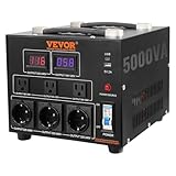
- 5000W Voltage Converter Transformer: This step up down transformer features 6 AC plugs, including 3 US NEMA 5-15R 3-Pin output sockets, 3 European Shucko output sockets, 1 5V USB port, and 1 Type-C jack. It is built with 2 LED displays showing the current output voltage in real-time to avoid transformer overload. Please note: This converter is designed only for European/Asian 220V (single phase). It will NOT work with American 220V.
- Advanced Step-Up/Down Technology: By adjusting the input voltage switch, you can step up the input voltage from 110 volts to 220 volts or step down from 220 volts to 110 volts. Please switch to the correct voltage before powering on. Universal power wiring slot allows you to purchase a separate power cord to connect and use according to the jack in different countries.
- CE & FCC Certification: Our step up down converter have CE and FCC certification, so you can use them with more peace of mind. It is equipped with internal overload protection, overcurrent protection, and short circuit protection to reduce the risk caused by improper use effectively.
- Efficient & Quiet Operation: This voltage converter transformer adopts high-quality toroidal coils for 7x24 hours of continuous operation, which helps reduce noise, odor, and product weight effectively. It runs quietly and provides precise voltage to power your devices without problems or damage. (For the best experience, it is recommended to purchase a voltage converter with a load power at least 25% higher than the total power of your device)
- Portable & Compact Design: The step up step down transformer size is 10.6 x 9.5 x 8.5 in/270 x 240 x 215 mm, not taking up too much space. With an 28.2 lbs/12.8 kg net weight and convenient handle design, it is easy to carry and transport without effort.
230/240 V input
Primary:
H2 ─── H3
Supply line ─── H1
Supply return ─── H4

Secondary:
Load across X1 and X2
115/120 V input
Primary:
H1 ─── H3
H2 ─── H4
Supply line ─── H1/H3
Supply return ─── H2/H4

Secondary:
Load across X1 and X2
These diagrams are valid only if the transformer follows the stated H-terminal numbering and phasing. They are not a safe substitute for the actual product diagram.
Independent reader supportYour contribution helps us test, update, and keep practical guides available for everyone.What happens if the wrong connection is used?
- Higher voltage applied to a primary configured in parallel for lower voltage: the windings can be overexcited, causing excessive current, overheating, loud humming, insulation damage, or failure.
- Lower voltage applied to a primary configured in series for higher voltage: the secondary will generally be lower than its rated value, although the exact result depends on the design and load.
- Incorrect phasing in parallel: the windings can oppose each other and behave like a fault, producing high current and possible damage.
- Only one winding energized: a dual-primary transformer may produce an unexpected output and may overheat if the winding is not rated for the applied conditions.
- Wrong frequency: a transformer designed for 50 Hz must not automatically be assumed suitable for 60 Hz, or vice versa. Frequency must match the rating.
Testing the secondary after wiring is confirmed
Only after a qualified person has verified the primary connection, protection, enclosure, and access controls:
- Energize through appropriate overcurrent protection.
- Keep exposed terminals inaccessible.
- Measure AC voltage across the two secondary leads—not from an arbitrary lead to ground.
- Compare the no-load reading with the marked nominal voltage.
- Test again under the intended load.
- Watch for abnormal hum, rapid heating, smoke, odor, or nuisance tripping.
- De-energize immediately if anything abnormal occurs.
No-load secondary voltage may be higher than the nameplate value because transformer regulation causes voltage to fall under load. A small no-load difference is not automatically evidence of incorrect wiring.
Troubleshooting symptoms
The transformer hums loudly or trips the breaker
Possible causes include the wrong primary voltage, incorrect parallel jumpers, reversed phasing, a damaged winding, excessive inrush, a shorted load, wrong frequency, or unsuitable protection. Do not repeatedly reset the breaker. Isolate the supply and compare every connection with the manufacturer diagram.
Crashes, No Sound, or Screen Glitches?
Random freezes, missing sound and display glitches usually trace back to one bad driver. Find and replace yours safely.Free scan · under a minuteWindows Errors? Fix Them Before They Spread
Repair common Windows errors and clear accumulated junk for a smoother, more stable PC - no reinstall needed.Free scan · no reinstallThe secondary voltage is about half the expected value
Check whether only one primary half is energized, whether a series-connected primary is being supplied with the lower voltage, whether the model was misidentified, or whether the load is excessive. Confirm the secondary rating rather than assuming it from the wire count.
The secondary voltage is about twice the expected value
This can occur when a primary configured in parallel for the lower voltage is supplied with the higher voltage. De-energize immediately and investigate the input rating and jumper arrangement.
There is no secondary voltage
With power removed, check primary and secondary continuity, the primary protective device, jumper placement, a possible thermal protector, and whether the secondary is shorted. An open thermal protector may indicate overheating rather than a simple wiring fault.
There are strange voltage readings to ground
A floating secondary can show ghost or capacitive voltages on a high-impedance digital multimeter. Measure across the actual secondary terminals and interpret the result according to the transformer’s grounding design. Do not ground a secondary lead merely to make the reading appear normal.
Do these 3 things before closing this tab:
1Clear out junk files and repair common Windows errors2Fix the driver behind crashes, sound loss and screen glitches3Repair Windows errors before they cause bigger problemsCan the transformer be backfed?
Some transformers can be energized from their nominal secondary to produce a higher voltage at the nominal primary, but this is not automatically permitted. Use reverse operation only when the manufacturer specifically documents it or marks the transformer as bidirectional.
Backfeeding can produce higher-than-normal inrush current and nuisance operation of protective devices. Eaton’s installation guidance distinguishes transformers marked “bi-directional” from units not approved for reverse feeding. A control transformer or ordinary unidentified transformer should not be assumed suitable for this use.
Quick Recap
When to stop and call a qualified electrician
Stop rather than guess if:
- The nameplate or model number is missing;
- The primary voltage is unknown;
- The four wires do not clearly form two isolated winding pairs;
- Phasing is not confirmed for a proposed parallel connection;
- Insulation is damaged, burned, wet, or contaminated;
- Primary-to-secondary continuity is present and the construction is not understood;
- The transformer is connected to building wiring or a high-energy supply;
- The installation requires grounding, bonding, or code interpretation;
- The transformer is intended for commercial, industrial, medical, or other regulated equipment.
Quick-reference checklist
- Identify the exact manufacturer and transformer model.
- Read the nameplate and wiring diagram.
- Confirm the supply voltage and frequency.
- Confirm whether the two primary windings are permitted to operate in series or parallel.
- Group unknown leads only with the transformer de-energized.
- Confirm phasing before parallel operation.
- Verify secondary voltage, current, and VA rating.
- Do not assume colors, polarity, neutral, or grounding from appearance.
- Install appropriate protection, enclosure, conductors, grounding, and disconnects.
- Test only after the connection has been verified by a competent person.
Product prices and availability are accurate as of the date/time indicated and are subject to change. Any price and availability information displayed on Amazon at the time of purchase will apply.

