The safest way to build a custom terrarium controller is to treat it as a low-voltage environmental automation system—not as a board that directly connects every appliance. Use an ESP32 development board, a replaceable temperature-and-humidity sensor, protected MOSFET outputs for low-voltage DC loads, and an external certified power supply. Keep mains equipment outside the custom PCB.
The PCB is only one part of the project. Reliable results come from the chain of decisions that precedes it: define the enclosure and its biology, measure the real loads, design safe control behavior, prototype with modules, then validate the assembled board in the humid environment where it will operate.
As an Amazon Associate I earn from qualifying purchases.
Start with the terrarium, not the components
“Automate the terrarium” is not yet an electrical requirement. A tropical plant enclosure, orchid case, moss display, bioactive reptile habitat, and sealed decorative terrarium may need very different control strategies.
The Tool Desk
Outbyte PC Repair FREEClear out junk files and repair common Windows errorsFree Scan →Outbyte Driver Updater FREEScan for outdated or missing drivers - takes under a minuteDriver Scan →Before opening KiCad, write down:
- What is being controlled: temperature, humidity, lighting, ventilation, misting, watering, or a combination?
- Which loads are present, and what voltage and current does each require?
- Must an output be simply switched, or does it need PWM dimming?
- Should the system use Wi-Fi, or must it operate independently when the network is unavailable?
- Is data logging, a display, or local buttons required?
- What should happen after a power interruption?
- What is the safe state if a sensor disconnects or reports implausible data?
- Can condensation or splashing reach the electronics?
Separate the control objective from its implementation. “Keep humidity between two limits” is a requirement. Choosing a particular digital sensor is an implementation decision that must still be evaluated for placement, condensation tolerance, cable length, availability, and software support.
#1 Best Overall

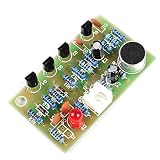
- Compatible with: Game Boy Zero GB DMG-01
- Package include: 1 x Button Board
- Please carefully check the picture, type, applicable model and color of the product before purchase to see if it is what you need. Enjoy your shopping.
- No technical support. Please make sure you know how to use it before buying.
Make a load schedule
| Load | Typical questions | Potential consequence of failure |
|---|---|---|
| Fan | Voltage, running current, startup current, PWM requirement? | Reduced ventilation or excess drying |
| Mister | DC or AC, pulse duration, water shutoff behavior? | Excess humidity or water damage |
| Pump or valve | Stall current, inductive transient, dry-run risk? | Flooding or pump damage |
| LED lighting | Strip voltage, maximum current, dimming method? | Loss of lighting |
| Heater | Power, thermal runaway risk, independent protection? | Overheating or fire risk |
Use the exact nameplate or datasheet values. Average running current is not enough: motors and pumps can draw substantially more during startup or stall.
Reference architecture
12 V certified adapter
   ├── fuse and reverse-polarity protection
   ├── protected 12 V outputs for fan, pump, mister or valve
   └── buck regulator → logic rail

ESP32 controller
   ├── I2C temperature/humidity sensor
   ├── MOSFET output: fan
   ├── MOSFET output: mister
   ├── MOSFET output: pump
   ├── MOSFET output: lighting
   └── buttons, LEDs, display and network interface
A 12 V input is a convenient reference architecture when the selected actuators are 12 V, but it is not universal. If the loads use 5 V, 24 V, or mixed voltages, document those rails separately and prevent accidental connection of one load to another rail.
For a first revision, use an ESP32-DevKitC or comparable ESP32 development board mounted with headers or a socket. Espressif describes the DevKitC as including the module support circuitry, USB-UART interface, reset and boot controls, regulator, USB connector, and accessible GPIO. That reduces the risk of simultaneously debugging the wireless module, USB interface, boot circuit, and terrarium hardware.
Development board or bare module?
A development-board carrier is larger and duplicates some circuitry, but it provides USB programming, easier replacement, and a lower-risk first prototype. A bare ESP32 module produces a smaller, cleaner board and may make sense for a later production revision, but it requires careful treatment of power, reset, boot strapping, flash, antenna clearance, programming, and RF layout.
Espressif provides official hardware resources, KiCad libraries, and design guidance, as well as DevKitC reference schematics, layouts, Gerbers, BOM files, and libraries. Use those materials for the exact module and board rather than copying a generic ESP32 pinout.
Design safe control behavior before writing firmware
A controller should not react to every small sensor fluctuation. Misting, fans, pumps, and heaters need bounded behavior.
- Hysteresis: use a lower threshold to start an action and a higher threshold to stop it.
- Minimum on-time: prevent rapid switching and allow a pump or mister to operate meaningfully.
- Minimum off-time: reduce wear and allow droplets or humidity to distribute.
- Maximum runtime: turn off an actuator even when the expected sensor response does not occur.
- Plausibility checks: reject missing, impossible, stuck, or clearly invalid readings.
- Startup delay: keep outputs off until the controller has a valid reading.
- Manual override: test each output without depending on the automatic algorithm.
- Watchdog recovery: recover from firmware hangs with safe output defaults.
- Power-loss recovery: restore schedules cautiously instead of activating every output immediately.
If humidity < 75%:
    start misting only if the 30-minute lockout has expired
    run for no longer than 20 seconds

Stop misting when:
    humidity >= 82%
    or maximum runtime is reached
    or the sensor becomes invalid

If the sensor is unavailable:
    disable automatic misting
    raise an alarm
    retain manual control only
These values are illustrative starting points, not universal terrarium settings. Species, enclosure volume, ventilation, substrate, sensor location, and actuator capacity determine suitable thresholds and timings.
Coordinate ventilation and humidity rather than making them fight each other. A strong fan can dry an enclosure while the mister is trying to raise humidity. Ventilation may need a minimum schedule for air exchange, while misting should use short, bounded pulses. Humidity alone is not a complete measure of air quality.
Choose and place the sensor
A well-placed sensor is often more useful than several poorly placed ones. Mount the temperature-and-relative-humidity sensor inside the enclosure but away from the direct mist stream, heating elements, LED heat, and warm regulator components. Avoid locations where droplets can condense directly on the sensing element.
Use a connector so the sensor can be replaced or moved. A small ventilated protective enclosure may help, provided it does not trap stagnant air. Keep I2C cables short enough for reliable operation; long wires, excessive capacitance, and unsuitable pull-ups can make the bus intermittent. For a remote sensor, consider a more robust physical interface rather than simply extending a fragile bus.
Calibration cannot fix a sensor mounted beside a nozzle or inside a warm electronics box. Compare readings with a trusted reference under controlled conditions, and remember that condensation tolerance, documented accuracy, library support, replacement availability, and cable behavior may matter more than a headline accuracy figure. A second sensor can reveal gradients or a failed reading, but it also adds calibration and control complexity.
Outdated Drivers Are Slowing You Down
One free scan finds every outdated or missing driver and matches the right update for your exact hardware.Free scan · exact hardware matchPC Slower Than It Used to Be?
A free scan shows the junk files, broken settings and background clutter dragging Windows down - then fixes them in one click.Free scan · Windows 10 & 11Design the power tree first
Create a power budget before selecting traces, connectors, or regulators:
Total supply current = controller + sensor + all loads that may run simultaneously
Supply power = supply voltage × total current
Design current = calculated maximum × engineering margin
Include startup and stall current, USB peripherals, regulator heating, and likely future additions. Do not size a supply from average consumption. A USB supply may power an ESP32 but still be unsuitable for pumps, misters, fans, and LED strips operating together.
A practical low-voltage board should consider:
- Input fuse or resettable protection
- Reverse-polarity protection
- Appropriate transient suppression
- Bulk capacitance near actuator outputs
- Local ceramic decoupling near ICs
- Separate actuator and logic current paths
- Clearly marked voltage and connector polarity
- Connectors rated for the expected current
- Strain relief, cable glands, and drip loops
- Test points for input, logic rail, ground, and important outputs
Use an external certified low-voltage adapter for a hobby project. Integrating an AC supply onto the PCB introduces mains hazards, creepage and clearance requirements, thermal problems, enclosure obligations, and possible compliance work.
Rank #3

- Compatibility: Specifically designed as a replacement for Mini Pro scooter, this control board ensures good compatibility and dependable performance, enhancing the overall functionality of your self balancing scooter.
- Stable and Dependable Performance: This stable and dependable control board significantly improves the stability and security of your scooter, allowing for a smooth and controlled riding experience.
- Accurate Control System: Equipped with a highly accurate control system, this board ensures that your self balancing scooter operates smoothly, providing good maneuverability and responsiveness for the .
- Easy Installation: It can be installed quickly and effortlessly, with straightforward steps that do not require professional skills, making it easy for anyone to replace and upgrade their scooter.
- Sturdy Construction: Made from premium aluminum alloy and PCB materials, this board is built to last and withstand the rigors of daily use, ultimately extending the lifespan of your self balancing scooter.
Use MOSFET channels for low-voltage DC loads
A typical low-side channel is arranged as follows:
Load positive  → supply positive
Load negative  → MOSFET drain
MOSFET source  → power ground
ESP32 GPIO     → gate resistor → MOSFET gate
Gate           → pull-down resistor → ground
For each MOSFET, verify logic-level operation at the ESP32’s actual gate voltage, drain-source rating above the supply and expected transients, continuous and pulsed current, and RDS(on) at the available gate voltage. Check thermal dissipation on the actual PCB. A headline current rating often assumes a large heatsink or favorable test conditions that a compact board cannot reproduce.
Use a gate pull-down so the load remains off while the controller is resetting or booting, and choose GPIOs whose startup behavior is safe. A gate driver may be necessary for larger loads or fast, high-current PWM.
Pumps, valves, relays, and other inductive loads require a correctly oriented flyback diode or suitable transient-suppression network. Rate the diode for the coil current and voltage. An LED strip and a pump are not electrically identical merely because both can be switched with a transistor.
When a relay is appropriate
Relays can make sense for galvanic isolation, unusual load types, or voltages and currents outside the comfortable range of a MOSFET. They are larger, slower, noisier, and subject to contact wear. Contact ratings must also account for motor startup current.
For mains-powered equipment, keep household AC wiring off this custom board. Use a certified, enclosed smart plug, timer, or relay device, and use a low-voltage interface only where the external device is designed to accept it. Mains work should be performed or checked by a qualified person. Exposed mains screw terminals have no place on an informal terrarium controller.
Quick wins for a faster PC:
Scan for outdated or missing drivers - takes under a minuteDriver Scan →Repair Windows errors before they cause bigger problemsFix Now →Draw the schematic in functional blocks
Organize the KiCad schematic into clear blocks:
- Power entry: connector, fuse, reverse-polarity protection, rails, and protection components.
- Controller: development-board headers or module, reset and boot access, and programming connection.
- Sensors: I2C pull-ups, sensor connector, and any external probe interface.
- Outputs: repeated MOSFET channels, gate resistors, pull-downs, and flyback protection.
- User interface: status LEDs, buttons, encoder, or display connector.
- Connectivity: antenna keep-out and USB access.
- Diagnostics: test points, fault indicator, and optional voltage or current monitoring.
Use net labels and repeated blocks instead of a dense diagram full of crossing wires. Put connector pin names, polarity, and voltage warnings directly on the schematic. Run electrical-rule checks, then review every connector against the physical wiring plan.
Assign GPIOs deliberately
GPIO choices vary by ESP32 family, module, development board, and boot-strapping behavior. Do not publish or copy a generic pin table as though it applies to every ESP32 variant.
Rank #4
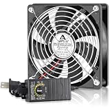
- Waterproof Fan with Speed Controller: IP67 rating 120mm computer fan with ac plug are built to withstand the humid dust exist harshest outdoor environments; use device smoothly without worrying about rain, splashes, dusty conditions, or brief submersion
- Efficient Cooling: 120mm waterproof fan designed for projects in high humidity or hot confined spaces that requires cooling or ventilation; Such as RV fridge, Grow Tent, Terrariums, Vivarium, Biltong Box, Solar Battery Box, AV Cabinet
- Speed Adjustable: an variable speed controller with fine tuning knob allows you to freely adjust the computer cooling fan speed according to your needs; whether you require powerful cooling or a quiet work environment
- Built to Last Dual Ball Motor: The fan's pcb board and whole motor are iscoated with a cured layer of adhesive film for protection against moisture, water and dust; ip67 fan are designed for maximum airflow and heat dissipation to keep the air circulating
- Easy to Install: Includes a 120 mm 12v dc ip67 waterproof cooling fans; 2x metal fan grills; 1x variable speed controller; 4x screws nuts; you can install the fan laid flat or stand upright to keep internal components cooler; rated at up to 50,000 hours
| Function | Selected GPIO | Checks |
|---|---|---|
| I2C SDA | Document the chosen pin | Boot conflicts, pull-ups, cable length |
| I2C SCL | Document the chosen pin | Boot conflicts, pull-ups, bus loading |
| Mister MOSFET | Document the chosen pin | Safe boot state |
| Pump MOSFET | Document the chosen pin | Safe boot state |
| Fan PWM | Document the chosen pin | PWM capability and frequency |
| Button or LED | Document the chosen pin | Pull-up, pull-down, and startup behavior |
| Programming serial | Board-defined | Avoid USB-UART conflicts |
Review the selected device against Espressif’s ESP32 schematic checklist and the current documentation for the exact board and silicon variant.
Lay out the PCB for current, moisture, and radio performance
Divide the board into an RF/controller zone, a sensor and low-noise zone, a power-entry zone, a MOSFET/output zone, and a connector edge. Put mounting holes and enclosure keep-outs into the design before final routing.
Keep the ESP32 antenna clear of copper, ground pours, tall components, metal brackets, and nearby enclosure material that could detune or obstruct it. Espressif recommends four layers for ESP32 PCB work while documenting circumstances in which a two-layer design can be used. A small two-layer hobby board can be practical if it preserves a continuous ground area and keeps the RF region clean. See Espressif’s PCB layout guidance.
Route actuator current directly from power entry to the output connectors. Keep pump and fan switching returns out of the sensor and ESP32 ground path. Use wider traces or copper pours for high-current paths, place bulk capacitors where they are effective, and avoid routing switching edges alongside the I2C bus.
The PCB is not waterproof by default. Keep it outside the wettest part of the enclosure, install it in an appropriate external enclosure, and provide drip loops and strain relief. Conformal coating may help in some environments, but it can interfere with connectors, buttons, sensors, antennas, and repair work. Never coat the sensing element unless its manufacturer explicitly permits it.
Prototype the system before ordering
- Write the enclosure, load, and safety requirements.
- Buy the intended power supply, actuators, sensor, and ESP32 board.
- Test every actuator independently.
- Measure steady-state, startup, and stall-related current where practical.
- Prototype one MOSFET channel.
- Test the sensor in its intended physical location.
- Implement hysteresis, timing limits, manual control, and fault handling.
- Draw and review the complete schematic.
- Check footprints, pin assignments, connector orientation, and component availability.
- Lay out the PCB and run electrical-rule and design-rule checks.
- Order a bare-board or assembled prototype.
Use KiCad’s official documentation and support resources for schematic capture, PCB layout, 3D inspection, and manufacturing-file generation. A fabrication service such as JLCPCB may advertise low prototype prices, but the bare-board price is not the project total. Add components, assembly, stencil, shipping, taxes, tools, and failed revisions.
Free tools Windows power users keep installed
One-click scans. No signup required.
Manufacture and assemble with revision one in mind
Export verified Gerbers and drill files. For assembly, check the BOM, footprints, component rotation, alternate parts, and stock status. If using automated assembly, upload the correct component-placement data and inspect the generated quote rather than assuming a headline setup price represents the complete cost. JLCPCB lists assembly pricing from an advertised setup charge plus per-joint pricing, but the actual quote depends on the full design and sourcing choices.
Best Value
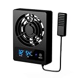
- [SMART AIR CIRCULATION] Improve airflow inside your reptile with steady ventilation that helps prevent stagnant air and supports a fresher enclosure environment. This compact fan circulates air throughout terrariums breeding boxes and rainforest style habitats while keeping your pet’s space comfortable.
- [AUTOMATIC CLIMATE CONTROL] Set your preferred temperature and humidity thresholds with the simple digital controls. When conditions your selected limits the fan activates automatically to help reduce overheating and excess so reptiles can enjoy a more balanced living environment.
- [CLEAR LED MONITORING] Transparent dual LED displays provide convenient real time visibility of changing temperature and humidity conditions. The precise probe sensor continuously checks the environment helping you make informed adjustments without repeatedly opening the enclosure.
- [QUIET STABLE DESIGN] Built for calm pet spaces this low noise fan operates smoothly while expelling warm air and supporting comfortable ventilation without unnecessary disturbance. The non slip silicone base helps keep the unit firmly positioned on a shelf or enclosure surface.
- [EASY CUSTOM SETTINGS] Press the responsive buttons to set temperature and humidity targets according to your pet’s needs. Set a threshold to zero when continuous ventilation is preferred. Measuring approximately 4.45 by 3.35 by 0.98 inches the ABS unit fits easily into many reptile habitats.
Hand-soldering large through-hole connectors, terminal blocks, and unusual mechanical parts on the first revision can make debugging easier. Leave accessible test points and do not bury every connection beneath the development board.
Bring up the board in a low-risk order
- Inspect the board for solder bridges, reversed parts, damaged connectors, and incorrect footprints.
- With power disconnected, check resistance between each supply rail and ground.
- Connect a current-limited source or otherwise limit the available fault energy.
- Power the board with pumps, heaters, misters, fans, and lights disconnected.
- Verify input polarity, fuse behavior, regulator output, and logic-rail voltage.
- Program the ESP32 and confirm USB communication, reset, and boot behavior.
- Read the sensor and check that invalid or disconnected readings are detected.
- Test each output with a safe substitute load.
- Add real loads one at a time, measuring voltage drop, reset behavior, and MOSFET temperature.
- Test simultaneous loads only after individual channels pass.
A successful bench power-up does not prove that the design is ready for a humid enclosure.
Minimum firmware feature set
Whether the firmware is written with Arduino, ESP-IDF, or another platform, it should provide:
Do these 3 things before closing this tab:
1Repair Windows errors before they cause bigger problems2Fix the driver behind crashes, sound loss and screen glitches3Clear out junk files and repair common Windows errors- Periodic sensor sampling and timeout detection
- Hysteresis-based control
- Minimum on and off times
- Maximum actuator runtime
- Boot-safe output states
- Manual output test mode with an automatic timeout
- Persistent configuration storage
- Timekeeping for lighting schedules
- Watchdog recovery
- Local autonomous operation when Wi-Fi is unavailable
- An event log for sensor faults, resets, and actuator activations
Wi-Fi can provide a dashboard, alerts, or configuration, but it should not be required for safe ventilation or bounded misting. Add OTA updates only after establishing a reliable physical or other recovery path.
Validate the installed system
Use a test matrix rather than stopping when the PCB powers on.
Electrical tests
- Input polarity, fuse operation, and no-load current
- Logic-rail voltage under load
- Maximum expected actuator current
- MOSFET temperature and output voltage drop
- ESP32 resets when a motor starts
- Brownout and power restoration behavior
- USB programming after assembly
Sensor tests
- Room-condition readings and comparison with a trusted reference
- Response to enclosure changes
- Sensor disconnection
- I2C short, bus lockup, and long-cable behavior
- Condensation exposure and recovery
- Whether the sensor location represents the plant or animal environment
Control and environmental tests
- Humidity below and above each threshold
- Pump unplugged or unable to change humidity
- Actuator stuck on
- Network unavailable
- Controller reboot during misting
- Power loss and restoration
- Simultaneous loads
- Manual override timeout
- Several days of continuous operation
- Water ingress, condensation, corrosion, and false triggers
What revision two might improve
Once the first revision has real operating data, useful additions may include current sensing, per-output fuses, a remote sensor board, a fan tachometer input, enclosure-temperature monitoring, an RTC or backup timekeeping method, stronger transient protection, a heater interlock, or an expansion connector. Add features because a measured limitation justifies them—not simply to increase the feature count.
When a custom PCB is unnecessary
A custom board is not automatically safer, cheaper, or more reliable. For one enclosure, a development board combined with commercial timers, enclosed low-voltage controllers, or certified smart plugs may be the better engineering decision. Avoid a custom PCB when immediate reliability matters more than learning, when the project involves mains switching, or when the cost of debugging and revising exceeds the value of integration.
Recommended Free Tools
Build the custom board when the project benefits from repeatability, clean connectorization, integrated low-voltage outputs, local autonomy, learning, or multiple identical installations. The strongest design is the one whose electrical architecture matches the terrarium’s actual hazards and operating requirements.
Quick Recap
Product prices and availability are accurate as of the date/time indicated and are subject to change. Any price and availability information displayed on Amazon at the time of purchase will apply.

