Crashes, No Sound, or Screen Glitches?
Random freezes, missing sound and display glitches usually trace back to one bad driver. Find and replace yours safely.Free scan · under a minutePC Slower Than It Used to Be?
A free scan shows the junk files, broken settings and background clutter dragging Windows down - then fixes them in one click.Free scan · Windows 10 & 11Use the reinforcement specified in the slab’s structural drawings and project specifications. Reinforcing bar (rebar) and welded wire reinforcement (WWR), commonly called welded wire mesh, are different products with different detailing and installation requirements. Neither is a universal substitute for the other, and the available technical guidance does not establish that one is always stronger, cheaper, or better.
The practical decision is whether the engineer’s required reinforcement can be fabricated, supported, and kept at the specified elevation and concrete cover during the pour. Confirm the design, slab type, governing code edition, quantities, laps, supports, access, and installed cost before ordering material. Do not change from bars to WWR—or from WWR to bars—without written design approval.
As an Amazon Associate I earn from qualifying purchases.
What the two reinforcement systems are
Reinforcing bar (rebar)
Rebar consists of individual steel bars identified by the size, grade, shape, spacing, and location shown on the structural drawings. Bars may run in one or more directions, be bent into specific shapes, or be detailed around openings, edges, joints, beams, columns, and other discontinuities. The placing drawings are the engineer’s construction instructions: the Concrete Reinforcing Steel Institute (CRSI) explains that they show where bars go and how they relate to the dimensions of the structure. See CRSI’s guidance on placing bars.
Free tools Windows power users keep installed
One-click scans. No signup required.
Because each bar is placed separately, a rebar layout can be adapted to concentrated demands and irregular geometry. That flexibility does not make an unspecified bar arrangement acceptable; bar diameter, grade, spacing, lap or development details, bends, and elevation all remain design requirements.
#1 Best Overall

- Valued Carpenter Pencil Set: You will get 2 pcs solid carpenter pencils with 26 piece 2.8 mm refills, 1 replaceable sharpener, 1 plastic storage box.The complete carpenter pencils combination allows you to finish your work faster and more easily
- Deep Hole Marker Pencil: The deep-hole construction pencils adopts 45mm elongated tip design, which is more convenient to mark in the small hole or in other tight areas that other carpenter markers cannot reach
- Carpenter Pencils with Sharpener: The sharpener is screwed into the top of the work pencil, which won't get lost either. Built-in pencil sharpener that keep the lead with pointed and smooth to Improves line of sight in fine work
- Stronger Solid Lead: This work pencil is matched with a 2.8 mm thick lead , which is much thicker and stronger during the drawing process of construction work, it will not break or damage easily
- Marks on Various Surfaces: 3 colors solid construction pencil can marks on various surfaces,such as metal, plastic, wood, paper etc. Ideals for woodworkers, contractors, craftsmen, builders, merchants and masons
Welded wire reinforcement (WWR)
WWR is a prefabricated grid of carbon-steel wires welded at intersections. It is supplied in sheets or rolls, with a specified wire designation and grid spacing. “Welded wire mesh” is common field language, but current ASTM terminology uses “welded wire reinforcement.” ASTM A1064/A1064M covers plain and deformed carbon-steel wire and WWR for concrete. The active listing identified when checked was ASTM A1064/A1064M-24; always verify the edition and locally adopted requirements when the specification is written.
WWR is not fence fabric, livestock mesh, drywall lath, or another generic wire product. The wire size, spacing, sheet or roll dimensions, welds, and material compliance must match the project documents. A grid that looks similar is not automatically an engineered concrete reinforcement product.
Why the drawings, not the material name, decide
Reinforcement is selected for the slab’s design demand and intended behavior. The documents should establish the reinforcement type, amount, layout, and position. Those requirements can include bar size and grade; WWR wire designation and spacing; the number of layers; laps and development; edge and opening details; supports; and required concrete cover.
A slab-on-ground, an elevated structural slab, and a pavement section may use steel differently. A slab-on-ground is supported by prepared soil or a base, while an elevated slab transfers loads through a structural system. Pavement reinforcement has its own detailing and joint considerations. Guidance about one category must not be treated as a design rule for another. CRSI’s pavement information is available at CRSI Pavements, but it does not replace the project engineer’s drawings.
Reinforcement also does not replace an adequate concrete mix, subgrade preparation, joints, curing, load-transfer details, or construction control. The steel can only perform as designed if the surrounding slab and its construction are properly specified and executed.
Rebar versus WWR: the decision factors
| Factor | What to verify for rebar | What to verify for WWR |
|---|---|---|
| Design function | Required bar areas, directions, shapes, grades, and locations shown on the drawings. | Required wire designation, grid spacing, orientation, sheets or rolls, and locations shown on the drawings. |
| Geometry | Individual bars can be cut and bent to scheduled shapes and detailed around openings or congested areas. | Sheet or roll dimensions, grid orientation, cutouts, overlaps, and access must fit the documented geometry. |
| Position | Bar supports and tying must keep every layer at its specified elevation and cover. | Supports must prevent sheets or rolls from being displaced by workers, hoses, and concrete placement. |
| Installation | Handling involves bundles, placing drawings, tying, chairs, and inspection of each bar and spacing. | Handling involves prefabricated mats or rolls, support layout, securing, overlap details, and safe movement over the reinforcement. |
| Specification | Use the specified reinforcing-bar standard, grade, size, shape, and fabrication requirements. | Use compliant WWR covered by the specified standard and designation; do not substitute generic wire. |
| Cost | Obtain a project estimate including steel, fabrication, supports, tying, labor, delivery, and waste. | Obtain a like-for-like estimate including WWR, cutting or rolling, supports, securing, laps, labor, delivery, and waste. |
| Substitution | Cannot be changed to WWR merely because the grid appears to contain a similar amount of steel. | Cannot be changed to bars merely because sheets are difficult to handle or unavailable. |
The table is a comparison framework, not a design conversion chart. A bar schedule and a WWR designation are not interchangeable descriptions of reinforcement.
How reinforcement position and concrete cover affect performance
Steel must remain where the design places it. Concrete cover is the concrete between the reinforcing steel and the exposed surface. CRSI describes cover as important for protecting reinforcing steel from corrosion when the work is properly constructed. The required cover depends on the member, exposure, and governing project requirements; it should be taken from the drawings and specification rather than guessed from a general rule.
Rank #2

- Ergonomically Designed: Work in tight areas with a compact design that gets into tough spots
- Both tools are designed to fit into difficult to reach spaces
- Complete a wide range of applications with a high-performance motor that delivers up to 300 UWO, and an impact driver delivering up to 1,400 in-lbs of torque
- Both the DEWALT impact driver and drill driver feature integrated LED work lights with a convenient 20-second delay, ensuring enhanced visibility in dimly lit or challenging work areas
- One-Handed Loading - Keep one hand free with a 1/4 in. hex chuck that accepts 1 in. bit tips
Supports establish the elevation before and during placement. CRSI examples include concrete blocks, plastic chairs, and wire supports. The support type must be stable on the prepared base and suitable for the specified cover and loading. A support that sinks, tips, or is spaced too far apart can leave reinforcement out of position even when the material itself complies.
Installing WWR in a slab-on-ground
For a slab-on-ground, the key control is to install and support the WWR before concrete is placed. The American Concrete Institute (ACI) states that ACI 301-20 requires WWR to be placed before concrete placement and supported as shown in the contract documents and in accordance with CRSI RB4.1. The applicable project specification and adopted code edition govern the work.
- Review the issued documents. Confirm the WWR designation, grid spacing, sheet or roll format, laps, edge conditions, openings, layers, elevation, cover, and support details. Resolve discrepancies with the designer before material is delivered.
- Prepare the base and access route. Complete the subgrade or base work required by the slab documents. Plan where workers, pump lines, carts, and finishing equipment will travel so the reinforcement is not used as a temporary roadway.
- Set supports before placing the steel. Lay out chairs, blocks, or other specified supports at a spacing that keeps the grid at the required elevation under expected construction traffic. Supports must rest securely and not puncture or destabilize the base.
- Place the sheets or rolls in the documented orientation. Keep the grid aligned with the drawings, provide the specified laps, and secure intersections or laps where the specification requires tying. Do not cut around an opening unless the detail permits it; install the documented additional or perimeter reinforcement.
- Inspect before the pour. Check designation, spacing, laps, cover, elevation, supports, edges, penetrations, and cleanliness. Photograph or record the inspection where the project quality plan requires it.
- Protect the installed position during placement. Use planned access boards, walkways, or other measures where specified. Recheck areas displaced by personnel, hoses, vibration, or concrete movement and correct them while correction is still possible.
ACI’s FAQ, “Placement of welded wire reinforcement (WWR) in a slab-on-ground,” quotes ACI 302.1R-15, Section 5.2.4: “Welded wire reinforcement should not be placed on the ground and pulled up after placement of the concrete, nor should the mats be walked in after placing the concrete.” The same passage says: “Proper support spacing is necessary to maintain welded wire reinforcement at the proper elevation; supports should be close enough such that welded wire reinforcement cannot be forced out of location by construction foot traffic.” Read the full response at ACI’s WWR placement FAQ.
Those quotations address a slab-on-ground practice specifically. They do not authorize a contractor to select a WWR designation, support arrangement, or cover for an unspecified slab.
What’s actually slowing this PC down?
Pick the symptom - the matching free tool is one click away.
The edition-specific support-spacing note
ACI’s FAQ also reports that ACI 301-16 limited support spacing to no more than 12 inches for WWR smaller than W4.0 or D4.0. That is an edition-specific provision, not a universal spacing rule. Apply it only when ACI 301-16 is the governing specification and the project conditions fit the provision; otherwise follow the current contract documents and adopted requirements.
Installing rebar in a slab
- Start with the placing drawings and bar schedule. Identify each mark, diameter, grade, length, bend, spacing, layer, lap, and location. Do not infer a bar arrangement from a typical slab or from the amount of WWR available locally.
- Verify fabrication and delivery. Check tags against the schedule, protect bars from damage, and stage bundles so the crew can place them without dragging steel across completed work or destabilizing the base.
- Install supports and establish elevation. Use the support types and spacing shown in the project documents. Supports must carry the bars and anticipated construction traffic while maintaining the specified cover.
- Place, tie, and secure the bars. Set bars in the required directions and layers, maintain spacing, complete laps and hooked or bent details, and tie enough intersections to prevent movement during concrete placement. The drawings control where ties and supplemental bars are required.
- Detail edges, joints, openings, and penetrations. Install the bars shown around recesses, drains, sleeves, columns, walls, and slab boundaries. Do not remove a bar to accommodate a penetration unless the designer provides a revised detail.
- Inspect before concrete placement. Confirm bar marks, size, grade identification, spacing, elevation, cover, laps, supports, cleanliness, and accessibility for the placing crew.
- Control traffic during the pour. Keep pumps, hoses, workers, and finishing equipment from shifting the cage or mat. If steel moves, stop and restore the designed position rather than assuming concrete will hold it there.
CRSI’s placing-bars guidance explains the relationship between placing drawings and construction and describes supports used to attain proper cover.
Can you use WWR instead of rebar?
Only when the engineer of record or other authorized design professional approves a documented substitution. A proposed change must demonstrate that the alternate system satisfies the same design intent for the specific slab, including reinforcement quantity, direction, spacing, anchorage or development, laps, crack-control requirements where applicable, elevation, cover, edge details, openings, and constructability.
Rank #3

- 【Great Compatibility】This Katerk 1/4 inch hex shank bit holder is specifically designed for 1/4 inch hex shank drill bits. It's compatible with most 1/4 fast hex handles, hex sockets, various electric screwdrivers, and handheld screwdrivers. The bit holder makes it a valuable addition for any handyman.
- 【Secure and Safe】Built with a secure backup nut design, each drill bit holder securely locks onto your bits, ensuring they stay firmly in place. Additionally, our bit holder incorporates a high-quality steel ball rolling design that holds up to several kilograms of weight, ensuring your various drill bits don't fall off.
- 【Easy One-Handed Operation】The bit holder for impact driver allows you to change bits single-handedly, simplifying your workflow. Its multi-color design further allows for quick identification of the drill bit you need.
- 【Compact and Convenient】Thanks to its compact size, this 1/4 inch bit holder is easy to carry around. The bit holder allows for easy attachment to various tools, making this a convenient addition to your construction accessories. The Katerk bit holder is cast from high-quality alloy material, promising a long product lifespan. Despite its rugged strength, the bit holder remains lightweight, making it portable.
- 【Cool Christmas Gift For Men Stocking Stuffers】 This screwdriver bit holder, driver bit holder, impact bit holder, can be given as a gift to your loved one, especially for anyone involved in construction or electrical work. It's a must-have for stocking stuffers for men and women, tools gifts for dad, tech gadgets for men, gifts for dad, gifts for him, gifts for husband, gifts for boyfriend, cool gadgets for men, and cool gifts for dad.
A visual comparison is not enough. A grid can have a large total length of wire yet fail to match the required steel area, spacing, orientation, or detailing. Conversely, a set of bars can contain a similar nominal steel area while behaving differently because its spacing, location, laps, or concentrated details differ. The project’s calculations, drawings, specifications, and approval process control the answer.
A practical substitution workflow
- Ask the general contractor or design team for the latest issued-for-construction drawings and reinforcement schedule.
- Describe the proposed change precisely: product standard, designation, sheet or roll dimensions, bar sizes, spacing, laps, supports, and affected locations.
- Have the engineer evaluate structural demand and detailing, not just material quantity.
- Obtain written approval and revised drawings or a formal response before ordering or placing the substitute.
- Update procurement, inspection, and placement plans so the approved system—not the originally bid system—is installed.
If material is unavailable, the correct response is a design clarification or substitution request. An installer should not solve a supply problem by choosing a visually similar product in the field.
Which option is easier to install?
There is no universal answer because labor and access vary. Rebar arrives as individual bars and can be shaped to complicated geometry, but crews must read placing drawings, set many pieces, tie them, and maintain supports. WWR arrives as prefabricated sheets or rolls, which can reduce individual-piece handling in suitable open areas, but large mats require planned access, adequate supports, controlled overlaps, and a crew capable of keeping the grid at elevation.
Site conditions can reverse the apparent advantage. Tight rooms, numerous penetrations, narrow strips, irregular boundaries, or congested structural details may make sheets difficult to fit. Large unobstructed slab areas may make prefabricated grids convenient, provided the specified product and support system are available. Delivery limits, crane or hoist access, roll handling, storage space, and worker safety belong in the installation plan.
Do not judge installation solely by how quickly steel can be spread on the base. The relevant result is reinforcement that remains at the required location through inspection and concrete placement.
How to compare installed cost honestly
The available technical sources provide no general, like-for-like cost statistic for rebar versus WWR. A meaningful estimate must be project-specific and include more than the purchase price of steel.
| Cost item | Questions to include in each quotation |
|---|---|
| Material | What exact bar grade and sizes, or WWR designation and spacing, are included? Are the quantities based on the latest drawings? |
| Fabrication | Are bar cutting and bending, WWR cutting, special shapes, or shop drawings priced separately? |
| Supports and securing | Are chairs, blocks, wire supports, tie wire, spacers, and replacement pieces included? |
| Labor | Does the price cover unloading, staging, placing, tying, overlap work, inspection corrections, and pour-day adjustment? |
| Delivery and handling | Are freight, equipment, hoisting, roll handling, storage, and remobilization included? |
| Waste and changes | How are offcuts, damaged material, late design changes, and approved substitutions handled? |
Request quotations against the same issued drawings and require suppliers to state exclusions. A lower material price can disappear if the system needs more supports, difficult handling, extra laps, or additional labor. A higher-priced product may still be appropriate if it is the specified design and materially reduces installation risk, but that is a project judgment rather than a general rule.
Rank #4

- Long Nib and Deep Hole Marker: Our mechanical carpenter pencil with 45mm nib is designed for easy marking of deep holes or narrow areas. These construction pencils are the great choice for woodworking tools, construction tools, carpenter tools, contractor tools, wood carpentry tools and architect tools
- Extra Refills in 2 Colors for Versatile Marking: The construction mechanical pencil comes with 12 extra 2.8mm refills, including 6 red and 6 black refills. The black refill is suitable for light surfaces, while the red wax is perfect for dark surfaces. Our carpenter mechanical pencil makes sure that you'll have an ample supply for extended use
- Built-in Sharpener: Our construction pencil comes with a built-in sharpener to ensure the mechanical pencil tip is always sharp and ready for use. Never buy an extra pencil sharpener again. A great tool for any woodworker pencil, contractor pencils. The refill can easily be extended or retracted with a simple click of the pencils mechanical, allowing you to work more efficiently and accurately
- Portable Clip Design: Our deep hole construction pencil features a portable clip design, easy to carry and attach to your pocket or tool box, so that you can keep the carpenter pencils mechanical close at hand, making it a convenient tool to have on the go. Great gifts choice for carpenters
- Stronger Pencil Lead: The black refills are made of lead, sturdy and smooth. The red refills are made of wax, clear and light. These marking pencils are much thicker and stronger than normal pencils during the marking process of construction work, suitable for various surfaces, such as glasses, metal, boards, floors, walls, furniture, etc. The written marks can be easily wiped with a wet paper towel when needed
Questions to settle before ordering
- Is the slab on ground, elevated, or part of a pavement design?
- Which structural drawings and specification revision govern?
- What reinforcement type, designation, grade, spacing, layers, laps, and edge details are shown?
- What concrete cover and elevation are required, and how will supports maintain them?
- Are sheets, rolls, or individual bars compatible with site access and available lifting equipment?
- Where will workers and concrete equipment travel during placement?
- Who will inspect and approve reinforcement before the pour?
- What is the written process for a material shortage or proposed substitution?
- Do local building requirements adopt a particular code or standard edition?
- Does the quotation include material, fabrication, supports, labor, delivery, and waste on a comparable basis?
Common failure modes and fixes
WWR is lying on the ground
Why it happens: Mats were placed before supports, supports sank, or the crew planned to pull the steel up during the pour.
Fix: Stop before placement, install stable supports at the documented arrangement, reset the WWR to the specified elevation, and obtain inspection approval. Pulling a grid upward through freshly placed concrete is not the recommended practice quoted by ACI.
Recommended Free Tools
Workers have walked the WWR out of position
Why it happens: There is no protected access route or supports are too widely spaced for construction traffic.
Fix: Provide the specified access and support arrangement, secure the affected areas, and recheck elevation and cover before and during the pour. The ACI quotation specifically connects support spacing with resistance to construction foot traffic.
Rebar cover is inconsistent
Why it happens: Missing, unstable, or unsuitable chairs; bars placed directly on the base; or traffic shifting the cage.
Fix: Replace or reset supports using the project detail, restore the bar layer and cover, and inspect before concrete placement. Do not rely on the concrete pour to correct a misplaced bar.
Do these 3 things before closing this tab:
1Scan for outdated or missing drivers - takes under a minute2Clear out junk files and repair common Windows errors3Fix the driver behind crashes, sound loss and screen glitchesThe delivered product does not match the schedule
Why it happens: A supplier quoted an informal “mesh” description, an outdated drawing was used, or tags were not checked.
Best Value
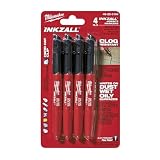
- Milwaukee Ink all Fine Point Marker, Black, 4 Per Pack
- 4 per pack Features Clog Resistant Marker Tip Writes through Dusty, Wet and Oily Surfaces Durable Marker Tip for Writing on Concrete, OSB and Rough Surfaces
- Clog resistant tip writes on dusty, wet and oily surfaces and is optimized for rough surfaces such as OSB, cinderblock and concrete
- Hard hat clip- attaches for easy access
- Quick dry time with reduced smearing and marking
Fix: Quarantine the material, compare tags and mill or compliance documentation with the current documents, and seek written design direction. Do not install a substitute based on appearance.
A field crew proposes “equivalent” reinforcement
Why it happens: A product is cheaper, easier to source, or believed to contain a similar quantity of steel.
Fix: Require a formal substitution request with design review. The engineer must evaluate layout and detailing as well as steel quantity.
Inspection checklist for the pre-pour hold point
- Latest approved drawings and schedules are available on site.
- Product tags, designations, grades, and documentation match the approved documents.
- Reinforcement is in the correct location, direction, layer, and elevation.
- Spacing, laps, bends, hooks, edge bars, opening details, and penetrations match the drawings.
- Supports are stable, correctly spaced for the project, and capable of maintaining cover under construction traffic.
- Steel is clean enough for the specified bond and free from materials that would interfere with placement.
- Access routes and pour sequencing will not displace the reinforcement.
- Any approved change is documented in writing and reflected in the inspection record.
Record corrections before releasing the concrete placement. The inspection is not a substitute for structural design; it verifies that the approved design has been translated into the work.
Standards and terminology to keep straight
Use “welded wire reinforcement” in specifications and submittals when referring to the concrete product. CRSI’s terminology resource, Reinforced Concrete Terminology, explains the distinction between reinforcement terms. ASTM A1064/A1064M is the relevant material specification identified for carbon-steel wire and WWR; confirm the edition adopted by the project and jurisdiction. CRSI also maintains a standards resource at CRSI Standards.
Standards do not by themselves select the reinforcement for a particular slab. They define material, fabrication, or construction requirements that must be applied alongside the project’s structural design, contract documents, and locally adopted code.
Bottom line for a project decision
Choose the system shown in the engineered slab documents. Rebar is a detailed arrangement of individual bars; WWR is a prefabricated welded grid. Either can be appropriate when designed, specified, supported, and installed correctly. The decisive questions are design demand, specified layout, elevation and cover, installation logistics, and total installed cost—not a general belief that one material is inherently superior. If a substitution is proposed, obtain written design approval before procurement or placement.
The Tool Desk
Outbyte Driver Updater FREEScan for outdated or missing drivers - takes under a minuteDriver Scan →Outbyte PC Repair FREERepair Windows errors before they cause bigger problemsFix Now →Quick Recap
Product prices and availability are accurate as of the date/time indicated and are subject to change. Any price and availability information displayed on Amazon at the time of purchase will apply.

