The short answer: this project turns a requested pen position such as (30, 120) into two servo angles using planar inverse kinematics. It uses two MG995 servos, four physical links, an Arduino, and a joystick to move a marker across a drawing surface.
It is best treated as an educational robotics and fabrication project—not as a precision plotter. The equations can be exact for the assumed geometry, but servo backlash, flexible sheet material, inaccurate holes, pen drag, and power problems all affect the physical result.
As an Amazon Associate I earn from qualifying purchases.
What inverse kinematics means
Forward kinematics asks: if the joints are at these angles, where is the pen? Inverse kinematics reverses the question: if the pen must reach this coordinate, what joint angles are required?
For this drawbot, the pen is the end effector. The Arduino receives an x and y target, calculates the geometry, and commands the two servos. The robot does not understand letters or drawings by itself; it understands the measured relationships among its pivots and links.
#1 Best Overall

- Intro to Robotics & Circuits: The kit includes motors, PCB microcontroller boards, and wires, by assembling and operating this robotic arm, It offers a fantastic first-time opportunity for children to know how electronic circuits work and control mechanical movement. Combining 3D puzzle with electrical enginnering, it's Fun and entertaining robotic science experiment for kids ages 8-14 and up! Note: 6 AA batteries needed but not included.
- Spark Interest in Engineering: This mechanical arm perfectly combines education with fun. Kids gain hands-on experience in physics & engineering principles while enjoying the thrill of building and play, making learning exciting. It sparks interest in future engineering and science pursuits.
- Challenging & Cool Wood Building Set! With wooden pieces and precise assembly tutorial, this wood building kit offers a satisfyingly complex building experience that enhances problem-solving skills, patience.
- Perfect Gift Idea: Designed for people who love to build and create, this DIY electronics kit for kids makes a gift or basker stuffer for boys and girls, tweens, teens, adults on birthday, christmas, easter, valentine day, also works for students in educational institutions, school science classes like science summer camping toy, or as STEAM game for families. It provides hours of challenging fun and a great sense of accomplishment once completed.
- STEM Project & Fun Toy for All Ages: No solidering required, the robot arm toy comes with all accessories you need to assemble this. Developing a lifelong love for science, the mechanical engineering kit is good for kids, teens, adults, boys and girls 8,9,10,11,12,13,14 years old and up
This is a constrained, two-dimensional solution. It is not a general-purpose 3D robot-arm system, and the pen’s orientation is mechanically constrained rather than independently controlled. For background on links, revolute joints, forward kinematics, and inverse kinematics, see the IEEE Robotics and Automation Society kinematics material.
What you will build
The mechanism has two motorized base pivots separated by a fixed distance. Each side carries two links, with a pen holder joining the distal linkage. In the published design, the nominal dimensions used by the code are:
- Two 100 mm links on each side.
- 60 mm between the actuator shafts.
- Two MG995 servos.
- An initial target position of
x = 30,y = 120.
Although the robot contains four physical links, it does not have four independently controlled degrees of freedom. Only two servo actuators are commanded.
Free tools Windows power users keep installed
One-click scans. No signup required.
The original Make: project lists approximately four hours of work, moderate difficulty, and a $50 project price. That price is a historical editorial estimate from the April 23, 2025 publication, not a verified 2026 shopping total. See the original project for the published build and diagrams.
Materials and fabrication files
Mechanical parts
- Base and top plate.
- Two first links and two second links.
- Two MG995 servos.
- Round metal servo horns.
- Pen holders.
- A thin whiteboard marker.
- Two 8 mm inside-diameter O-rings.
- F693ZZ, 8 mm bearings, spacers, bolts, standoffs, and locknuts.
The plates and links can be made from approximately 3 mm plywood, MDF, acrylic, or whiteboard material. The companion repository contains laser-cutter files, 3D-printable files, the main drawbot sketch, a circle-drawing sketch, and a ServoEasing-based Make-logo example.
Do not scale the files casually. The code assumes link lengths measured from pivot center to pivot center and a particular actuator spacing. If your material thickness, printed parts, servo bodies, or mounting holes differ, measure the assembled mechanism and update the software.
Electronics
- Arduino Uno or a compatible Arduino-style board.
- Two-axis analog joystick.
- Breadboard and jumper wires.
- Separate regulated 5 V, 2 A servo supply.
- USB cable for programming.
An Arduino Uno is a suitable controller for the published build. The official board reference is the Arduino Uno Rev3 product page, and the standard Arduino Servo library documentation covers servo attachment and commands.
Outdated Drivers Are Slowing You Down
One free scan finds every outdated or missing driver and matches the right update for your exact hardware.Free scan · exact hardware matchPC Slower Than It Used to Be?
A free scan shows the junk files, broken settings and background clutter dragging Windows down - then fixes them in one click.Free scan · Windows 10 & 11Rank #2

- Spark Your Creativity with Robotic Arm: Hiwonder-xArm1S is a high-quality desktop robot arm capable of remote-control grasping, object transportation, custom actions, graphical programming, and more. It serves as the ideal platform for building and showcasing creative projects and for learning about bionic robotics.
- Intelligent Servo: Hiwonder-xArm1S is equipped with 6 high-precision intelligent serial bus servos that provide position, voltage and temperature feedback. These powerful servos deliver strong torque, enabling the robot arm to grasp objects weighing up to 500g with ease.
- Premium Structure Design: The robot arm is constructed from an exquisite aluminum alloy bracket. The base is fortified with high-torque servos and industrial-grade bearings, guaranteeing exceptional stability.
- Various Control Methods: It supports PC, phone app, mouse, wireless PS2 Wireless Controller, and you can also control the robotic at your fingertips. With these control methods, xArm robotic Arm would bring more methods of play and study, perfect for realizing your innovative programming ideas and coding study.
- Versatile Action Editing: Hiwonder-xArm1S provides various action editing methods through a easy-to-use interface, including PC, app, and offline manual editing. This versatility allows you to easily create a wide range of robot applications.
Assemble the mechanism
- Inspect the files. Choose the DXF files for laser cutting or the 3D-printable files. Confirm that the intended material thickness matches your stock.
- Build the base. Join the base and top plate with eight M3 × 10 mm bolts and four M3 × 25 mm standoffs. Install the two servos without forcing the plates out of alignment.
- Center the servos before fitting the horns. Upload the neutral-position sketch below, power the servos, and wait until both reach 90 degrees.
- Mount the horns and first links. Match the design’s orientation and check that the left and right sides are mirror-correct.
- Install the distal links. Fit the bearings, spacer, bolts, and locknuts. The published design uses a 3 mm spacer in one linkage connection and describes the opposite side as using the same connection without that spacer.
- Fit the pen holder. Insert a thin whiteboard marker and use the O-rings for a light, compliant grip.
- Check movement by hand. With power removed, the linkages should move freely without binding, plate flex, or over-tightened locknuts.
Wire the electronics safely
Use the published pin assignment:
| Connection | Destination |
|---|---|
| Servo 1 signal | Arduino D3 |
| Servo 2 signal | Arduino D5 |
| Joystick X output | Arduino A1 |
| Joystick Y output | Arduino A0 |
| Joystick VCC | 5 V |
| Joystick GND | Ground |
| Servo red wires | External supply positive |
| Servo black wires | External supply negative |
| Arduino GND | External supply negative |
Do not rely on the Arduino 5 V pin or a weak USB supply to power two loaded MG995 servos. Servos can draw large transient currents and inject electrical noise. The servo supply and Arduino must share a common ground so the signal voltage has a common reference.
For a safer first test, disconnect the links and pen, secure the servo wires, and use a regulated supply with current protection where practical. Never deliberately stall a servo against a hard stop.
Center the servos before assembly
Upload this minimal sketch before attaching the horns:
#include <Servo.h>

Servo servoOne;
Servo servoTwo;

void setup() {
  servoOne.attach(3);
  servoTwo.attach(5);
}

void loop() {
  servoOne.write(90);
  servoTwo.write(90);
  delay(20);
}
Wait for both servos to reach neutral, then install the horns in the orientation shown by the fabrication design. A spline may not allow perfect mechanical alignment. If the arm is consistently offset, use software calibration offsets; if it is badly misaligned, remove and remount the horn instead of hiding the error in the equations.
What’s actually slowing this PC down?
Pick the symptom - the matching free tool is one click away.
The geometry behind the equations
Use this coordinate convention:
- Left actuator shaft:
(0, 0). - Right actuator shaft:
(d, 0). - Target pen position:
(x, y). d: distance between actuator shafts.linkOneandlinkTwo: measured link lengths.
For the nominal design, linkOne = 100, linkTwo = 100, and d = 60, in millimetres. The exact servo commands still depend on the servo orientation and the angle convention used during assembly.
1. Find the two pivot-to-target distances
From the left pivot:
c = sqrt(x*x + y*y);From the right pivot:
e = sqrt((d - x)*(d - x) + y*y);These are the hypotenuses of two right triangles.
2. Find the inner triangle angles
The published equations use arctangent:
alphaOne = atan(y / x) * (180 / PI);
betaOne  = atan(y / (d - x)) * (180 / PI);
For robust code, use atan2() instead. It handles quadrant information and avoids division by zero when x = 0 or x = d:
alphaOne = atan2(y, x) * 180.0 / PI;
betaOne  = atan2(y, d - x) * 180.0 / PI;
3. Use the law of cosines
The remaining angles come from the triangle formed by the two links and the pivot-to-target distance:
Rank #3

- Spark Your Creativity with Robotic Arm: Hiwonder-xArm1S is a high-quality desktop robot arm capable of remote-control grasping, object transportation, custom actions, graphical programming, and more. It serves as the ideal platform for building and showcasing creative projects and for learning about bionic robotics.
- Intelligent Servo: Hiwonder-xArm1S is equipped with 6 high-precision intelligent serial bus servos that provide position, voltage and temperature feedback. These powerful servos deliver strong torque, enabling the robot arm to grasp objects weighing up to 500g with ease.
- Premium Structure Design: The robot arm is constructed from an exquisite aluminum alloy bracket. The base is fortified with high-torque servos and industrial-grade bearings, guaranteeing exceptional stability.
- Various Control Methods: It supports PC, phone app, mouse, PS2 wireless control, and you can also control the robotic at your fingertips. With these control methods, Hiwonder-xArm1S would bring more methods of play and study, perfect for realizing your innovative programming ideas and coding study.
- Versatile Action Editing: Hiwonder-xArm1S provides various action editing methods through a user-friendly interface, including PC, app, and offline manual editing. This versatility allows you to easily create a wide range of robot applications.
alphaTwo = acos(
  ((linkTwo * linkTwo) - (c * c) - (linkOne * linkOne))
  / (-2 * linkOne * c)
) * 180.0 / PI;

betaTwo = acos(
  ((linkTwo * linkTwo) - (e * e) - (linkOne * linkOne))
  / (-2 * linkOne * e)
) * 180.0 / PI;
The final servo angles are combined differently depending on whether the target is left of the left shaft, between the shafts, or right of the right shaft. That is why the published code separates x < 0, 0 <= x <= d, and x > d. Do not copy the angle-combination signs into a modified mechanism without checking the servo orientation and linkage diagram.
Reject unreachable targets before calling acos()
For either two-link chain, the target distance must satisfy:
abs(L1 - L2) <= r <= L1 + L2With two 100 mm links, the nominal mathematical range is 0 to 200 mm from each pivot. The useful range is smaller because of servo travel, collisions, torque, pen contact, material flex, and awkward near-singular poses.
Add validation and cosine clamping:
bool reachable(double r, double L1, double L2) {
  return r >= fabs(L1 - L2) && r <= (L1 + L2);
}

double clampUnit(double value) {
  if (value > 1.0) return 1.0;
  if (value < -1.0) return -1.0;
  return value;
}
Check both c and e before calculating the angles. Floating-point rounding can produce a value such as 1.00001 for a mathematically valid triangle; clamping prevents that small error from turning into a NaN.
Test with a fixed coordinate first
Start without the joystick:
double x = 30.0;
double y = 120.0;
Print c, e, alphaOne, alphaTwo, betaOne, betaTwo, and the final servo angles to the Serial Monitor at 9600 baud. Move slowly and confirm that the pen reaches the expected region before adding manual input.
The Tool Desk
Outbyte Driver Updater FREEScan for outdated or missing drivers - takes under a minuteDriver Scan →Outbyte PC Repair FREERepair Windows errors before they cause bigger problemsFix Now →The published sketch attaches the servos to D3 and D5, reads the joystick on A0 and A1, and changes the target in 5 mm increments when readings cross approximate thresholds of 300 and 800. The code’s axis assignment is:
yval = analogRead(A0);
xval = analogRead(A1);
Joystick modules vary in orientation. Move one axis at a time while watching the serial readings, then reverse the corresponding software direction if necessary.
Rank #4
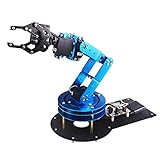
- Spark Your Creativity with LeArm Robotic Arm: LeArm is an elementary 6DOF desktop robot arm outfitted with 6 high-quality digital servos.It is capable of remote-control grasping, object transportation, custom actions, graphical programming, and more. It serves as the ideal platform for building and showcasing creative projects and for learning about bionic robotics.
- Anti-stall Protection: The robot arm end is equipped with 3 anti-blocking servos, complete with gear clutches that significantly extend the servos' lifespan.
- Premium Structure Design: The robot arm is constructed from exquisite metal bracket. The base is fortified with high-torque servos and industrial-grade bearings, guaranteeing exceptional stability.
- Various Control Methods: It supports PC, app, mouse and wireless handle control. Users can control the robot at your fingertips.
- Enjoy Robotic Arm Making: Enjoy the robot assembly process, LeArm is great for learning and building robot structures! Designed for students, engineers, university courses, and robot lovers. Comes with easy tutorials and simple programming software.
Make joystick control more stable
The original loop can update repeatedly while the joystick is held beyond a threshold. That makes speed depend on loop timing. A more usable controller adds:
- A deadband around the joystick’s center value.
- A fixed update interval using
millis(). - Small increments for fine adjustment.
- Software limits on both target coordinates.
- Servo-angle limits appropriate to the assembled mechanism.
For example, software protection may look like:
alphaFinal = constrain(alphaFinal, 5, 175);
betaFinal  = constrain(betaFinal, 5, 175);
These are example limits, not guaranteed safe limits for every MG995 installation. Determine the safe range with the linkage disconnected, then verify it under load without allowing the servo to hit a mechanical stop.
Recommended Free Tools
Also remove or correct any impossible threshold condition such as xVal > 800 && xVal < 200. No value can satisfy both comparisons. Separate tests such as if (xval > 800) and if (xval < 300) are the appropriate pattern.
Calibrate the physical robot
A calculated angle is not automatically the angle produced by the physical machine. Calibrate:
- Left and right servo offsets.
- Mirrored servo direction.
- Horn spline alignment.
- Actual pivot-to-pivot link lengths.
- Actual actuator spacing.
- Backlash and looseness.
Offsets can be applied at the final command:
servoOne.write(alphaFinal + leftOffset);
servoTwo.write(betaFinal + rightOffset);
Measure link lengths from pivot center to pivot center, not from the outside edges of the parts. Measure actuator spacing after assembly. A modified 3D-printed arm may require completely different values from the nominal 100 mm and 60 mm values.
Troubleshooting
Servos twitch, reset, or behave unpredictably
Disconnect the mechanism and test each servo independently. Confirm the separate 5 V supply, common ground, secure wiring, and absence of binding. Do not power loaded MG995 servos through the Arduino board alone.
Do these 3 things before closing this tab:
1Fix the driver behind crashes, sound loss and screen glitches2Repair Windows errors before they cause bigger problems3Scan for outdated or missing drivers - takes under a minuteOne side moves backward
Check whether the servo is mirrored or the horn was installed in the opposite orientation. You may need an offset or a reversed command such as 180 - angle, but verify the physical geometry before changing the mathematics.
Best Value

- ♥Robot Arm Building Kit: this mini robot kit will provide the required hardware and tools to show you how to build a robot kit step by step. NOTE: You need to prepare two batteries.
- ♥Flexible 4DF Arm Robot: The 4-axis design robotic arm is flexible and can grab objects in any direction. The clip can be opened 260°, the wrist can be rotated 180°, the elbow can be rotated 180°, and the base can be rotated 180°.
- ♥Easy To Build And Learn: we provide easy-to-follow assembly and programming tutorials, as well as quick-response after-sales and technical support.
- ♥Remember and Repeat Actions: not only the desk robot hand can be controlled by the joystick we provide, it can also record up to 170 actions and repeat these actions once.
- ♥Great Gift: this mini robot arm is a DIY electronic kit for Adults/Beginners/Teens to improve building, coding and programming skills.
The Serial Monitor displays nan
The target may be unreachable, an acos() argument may be outside -1 to 1, or the original atan(y/x) expression may be dividing by zero. Add reachability checks, use atan2(), clamp cosine inputs, and confirm the measured dimensions.
The mechanism binds
Look for misaligned plates, over-tightened locknuts, incorrectly seated bearings, incorrect material thickness, nonparallel horns, and inaccurate holes. Loosen and retighten while checking movement. Do not try to compensate for severe mechanical misalignment with software.
The pen reaches points but drawings are distorted
Check the actual link lengths and actuator spacing, then calibrate several known points. Reduce marker pressure, improve structural stiffness, and account for servo backlash. Smooth path interpolation and a pen-lift mechanism can help, but neither removes mechanical inaccuracies.
Quick wins for a faster PC:
Repair Windows errors before they cause bigger problemsFix Now →Scan for outdated or missing drivers - takes under a minuteDriver Scan →What this project can—and cannot—draw
The joystick demonstrates coordinate control. It is not yet an automated drawing pipeline. The published project does not by itself provide SVG parsing, bitmap tracing, path interpolation, pen-up/pen-down commands, acceleration planning, or closed-loop position feedback.
For automated drawings, the next additions would be a pen-lift servo, a computer or serial path sender, coordinate scaling, line interpolation, and controlled drawing speed. The repository also includes circle and ServoEasing examples; ServoEasing can make motion smoother, but software easing cannot eliminate backlash, flex, poor power, or inaccurate fabrication.
Accuracy expectations and upgrade paths
This drawbot is valuable because it makes the relationship between Cartesian coordinates and joint angles visible. It is not a high-accuracy plotting machine. Hobby servos have limited repeatability, the linkage can flex, and marker friction can amplify small errors.
If accurate rectangular plotting is the priority, a linear XY plotter is usually a better architecture, similar to the mechanisms used in many 3D printers and laser cutters. If angular repeatability and more advanced motion control are the priority, stepper motors with suitable drivers, homing, and mechanical reduction may be a better next step. For a general 3D arm, a robotics library such as the Python-oriented tools discussed in the IEEE material is more appropriate than extending these planar equations.
A practical acceptance test
Define success before modifying the design:
- Both servos reach neutral without excessive noise.
- The mechanism moves through its safe workspace without binding.
- At least several reachable fixed coordinates produce valid angles and no
NaNvalues. - The joystick moves the target in the intended directions.
- The pen can draw a simple square or circle without losing power or striking a mechanical stop.
- Repeated moves to the same coordinate show the expected level of servo and linkage repeatability.
That test distinguishes a functioning educational robot from a precision plotter. The design’s central lesson remains the same: measure the geometry, validate the workspace, calculate the joint angles, and calibrate the physical mechanism.
Quick Recap
Product prices and availability are accurate as of the date/time indicated and are subject to change. Any price and availability information displayed on Amazon at the time of purchase will apply.

