What’s actually slowing this PC down?
Pick the symptom - the matching free tool is one click away.
The right tool depends on the cable and the fault. A multimeter can confirm an open conductor, a toner can help trace the cable and suggest a fault area, and a time-domain reflectometer (TDR) can estimate the distance to an open or short from one end. None of these methods should be connected to an energized circuit unless the specific tester is rated for that condition.
For a removable low-voltage cable with both ends accessible, start with a visual inspection and multimeter tests. For a hidden cable where you need the distance to the fault, use a compatible TDR. Mains, buried, high-voltage, fire-alarm, safety-control, and other hazardous wiring should be handled by a qualified professional.
As an Amazon Associate I earn from qualifying purchases.
Safety first: isolate the cable
Before testing, disconnect both ends of the cable from equipment, power supplies, batteries, network switches, PoE sources, amplifiers, panels, and other circuits. Verify that no voltage is present with an appropriate tester.
Do not connect a continuity tester, ordinary ohmmeter, or general-purpose TDR to energized wiring. For example, Klein states that its 501-915 TDR Cable Length Meter is for unenergized cabling and is protected only up to 30 V peak AC/DC (Klein specifications). Follow the tester’s voltage rating and instructions rather than assuming that “low voltage” means safe.
#1 Best Overall
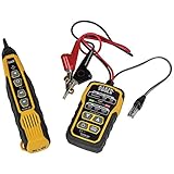
- PROFESSIONAL GRADE TONE GENERATOR: Includes a professional-grade analog tone generator and tracing probe for accurate and efficient tracing of low voltage, open-ended, non-energized wiring (<60V)
- VERSATILE TONE CADENCES: Toner-Pro features 5 distinct tone cadences and can transmit signals over 1,000 feet, ensuring reliable tracing capabilities
- SECURE WIRE ATTACHMENT: Rugged Angled Bed of Nails (ABN) clips securely attach to wires, providing a stable connection during tracing operations
- EASY CONNECTIONS: RJ11 plug easily connects to telephone and data jacks to transmit tone; works with RJ45 via center pins (4 and 5) for effective cable identification
- CONTINUITY AND POLARITY TESTING: Toner-Pro tests for continuity and polarity, with clearly labeled LEDs indicating the results for easy interpretation
Stop and call a qualified electrician or cable-fault specialist for mains wiring, panel circuits, buried power cable, high-voltage cable, fire-alarm circuits, elevator wiring, medical equipment, safety controls, or wiring that cannot be safely isolated.
First identify the cable and the actual fault
“The wire is broken” can describe several different problems:
- Open circuit: a conductor is no longer continuous.
- Short circuit: two conductors are touching.
- Short to shield, chassis, ground, or conduit: insulation has failed or a termination is incorrect.
- High-resistance connection: the conductor still passes a continuity test but causes voltage drop, heating, noise, or unreliable operation.
- Intermittent open: continuity changes when the cable bends, vibrates, heats, or is pulled.
- Insulation failure: a conductor leaks electrically to another conductor or ground.
- Termination failure: a plug, crimp, terminal, splice, or connector is faulty while the cable itself is intact.
- Impedance discontinuity: a splice, branch, bridge tap, crushed section, or damaged termination affects data or signal transmission.
Removable appliance leads, speaker cables, sensor wires, Ethernet, coax, automotive harnesses, in-wall cable, and power-distribution wiring require different testing and repair decisions. A TDR is not automatically suitable simply because a cable contains multiple conductors.
Do these 3 things before closing this tab:
1Clear out junk files and repair common Windows errors2Fix the driver behind crashes, sound loss and screen glitches3Repair Windows errors before they cause bigger problemsInspect the ends before opening the cable
Many apparent cable breaks occur at the ends. Examine plugs, strain reliefs, crimp terminals, screw terminals, patch panels, and connector pins for looseness, corrosion, bent contacts, pulled conductors, heat damage, and damaged insulation.
Pay particular attention to the first few inches behind a plug or connector, sharp bends, cable clamps, hinges, tie points, equipment entry points, and locations exposed to oil, water, heat, or vibration. If the cable is inexpensive and molded, replacement is often more reliable than trying to repair it.
Use a multimeter to confirm the fault
A multimeter can answer whether a conductor is continuous, whether its resistance is unusually high, and whether unwanted shorts exist. It normally cannot tell you that an inaccessible open is exactly 37 feet from one end.
Rank #2

- RELIABLE CIRCUIT TRACING: The Advanced Circuit Tracer Kit ensures dependable tracing of energized or non-energized breakers, fuses, and wires for accurate electrical identification
- ADJUSTABLE SENSITIVITY: Modify receiver sensitivity to detect through materials like drywall, cement block, shielded cable or underground (see manual for underground/shielded tracing instructions)
- VERSATILE APPLICATIONS: Trace wires, conduit, pipes, or isolate a single wire within a bundle, making it suitable for a wide range of electrical tracing tasks
- SIGNAL STRENGTH INDICATION: Audible beep and visual indicators on the receiver provide clear signal strength feedback, aiding in precise wire identification
- ILLUMINATION AND NCV FUNCTION: Receiver includes a built-in flashlight for low-light areas and a non-contact voltage (NCV) function to test wire energization, enhancing safety and visibility during tracing
End-to-end continuity and resistance test
- Disconnect and isolate the cable completely.
- Label the conductors or connector pins.
- Touch the meter probes together and note the lead resistance if you are measuring low resistance.
- Test conductor 1 from one end to the corresponding conductor at the other end.
- Repeat for every conductor.
- Record resistance rather than relying only on the continuity beep.
A low, stable reading generally indicates continuity, but there is no universal resistance value that defines a “good” cable. Acceptable resistance depends on conductor size, cable length, temperature, load, and the application. A cable can beep in continuity mode and still have too much resistance for a high-current circuit or too much degradation for a high-speed data link.
Free tools Windows power users keep installed
One-click scans. No signup required.
Check for shorts
With the cable still disconnected, test each conductor against every other conductor. If the cable has a shield or drain wire, test each conductor against the shield as well. For shielded or automotive wiring, also follow the equipment’s wiring diagram when checking against chassis or ground.
Use a temporary far-end loop
For a two-conductor cable with both ends accessible, temporarily connect the two conductors together at the far end. At the near end, measure resistance between them. A low, stable reading indicates that the test loop is complete. An open or unstable reading indicates a problem in one of the conductors, a connector, or the temporary jumper.
For multi-core cable, loop one conductor at a time or use a known-good spare conductor where appropriate. This confirms the path but does not provide a precise fault location unless you can divide the cable into sections or use a distance-to-fault instrument.
Test for an intermittent break
Monitor continuity or resistance while gently flexing the cable. Move it slowly rather than twisting it aggressively. Concentrate on strain reliefs, connector transitions, hinges, clamps, sharp bends, and visible damage.
For installed or automotive wiring, move accessible sections one at a time while watching the meter or the affected circuit. If the reading changes only during movement, heat, or vibration, treat the fault as intermittent even if the cable passes a later static test. Do not casually pierce insulation: probe holes can admit moisture and create a later corrosion failure.
Rank #3

- EASY WIRE TRACING: Simple analog tone generator and wire tracing probe for open-ended, non-active low-voltage wires, making wire tracing hassle-free (<60v)
- OPTIMIZE SIGNAL FOR BEST RESULTS: Separate wires when possible and use proper grounding to improve tone detection and accuracy
- ALLIGATOR CLIPS INCLUDED: Comes with alligator clips for easy connection to unterminated wires, providing convenience during testing
- RJ45 TO RJ45 TEST CABLE: Includes an RJ45 to RJ45 test cable for seamless connectivity during testing and wire mapping
- COMPREHENSIVE WIRE MAPPING: Toner and probe together perform a pin-to-pin wire map test, ensuring thorough wire mapping and identification
Use a toner or wire tracer to follow the route
A toner consists of a transmitter connected to the cable and a receiver used along its route. It is useful when you cannot identify a cable in a bundle, wall, ceiling, panel, or conduit.
- Isolate the cable unless the specific tracer is rated for the circuit condition.
- Connect the transmitter to the correct conductor, pair, shield, or reference.
- Confirm that the receiver detects the signal at a known-good point.
- Trace the route slowly and mark changes in signal strength or tone quality.
- Repeat from the opposite end where possible.
- Verify any suspected fault with continuity, resistance, or insulation testing before cutting into a wall or cable.
A sudden tone reduction can suggest an open or damaged area, but it is not proof of the exact break. Shielding, grounding, adjacent conductors, junctions, branches, cable geometry, and changes in cable condition can all affect signal strength. Fluke’s low-voltage procedure recommends tracing from both directions and checking whether the signal changes at the same location (Fluke wire-tracer procedure). A toner traces a cable; it is not equivalent to a TDR distance measurement.
Use a TDR to estimate distance to the break
A time-domain reflectometer sends a low-voltage pulse into an isolated cable. An open, short, splice, bridge tap, or other impedance change reflects part of the pulse. The instrument measures the round-trip travel time and converts it into an estimated distance.
The Tool Desk
Outbyte Driver Updater FREEFix the driver behind crashes, sound loss and screen glitchesFind Drivers →Outbyte PC Repair FREEClear out junk files and repair common Windows errorsFree Scan →The result depends heavily on the cable’s velocity of propagation (VoP), sometimes called velocity factor. If the wrong VoP is selected, the distance can be consistently wrong even when the TDR is working correctly. Distance is measured along the cable, not as a straight line through a wall, ceiling, building, or ground.
General TDR procedure
- Disconnect both ends of the cable from all equipment.
- Verify that the cable is not energized.
- Identify the correct conductor pair or conductor-to-reference connection.
- Select the closest cable type or enter the manufacturer’s VoP.
- Connect the TDR with the correct adapter and test leads.
- Record the distance to an open, short, or other reflection, plus the total cable length.
- Repeat the test from the opposite end.
- Compare the two readings. Where practical, the two fault distances should approximately add to the measured cable length, allowing for VoP error, connectors, and instrument accuracy.
- Inspect the smallest practical area around the calculated location.
- Repair or replace the cable, then test it again.
The reading is a search zone, not a guaranteed physical coordinate. Short cables, connector reflections, patch cords, branches, bridge taps, multiple faults, and a wrong VoP can make the result ambiguous. The first large reflection can also mask smaller faults farther along the cable.
Published equipment capabilities vary. Fluke’s TS90 is specified for two-or-more-conductor cables up to 2,500 feet and displays distance to opens or shorts (TS90 specifications). Klein’s 501-915 lists a maximum measurement range of 3,000 feet and approximately ±(2% plus 3 feet/0.9 m) accuracy under its stated conditions (Klein specifications). These are product-specific figures, not universal TDR accuracy.
Rank #4

- ACCURATE CIRCUIT BREAKER IDENTIFICATION: Quickly locate the correct breaker with precision using the transmitter and receiver of the circuit breaker finder, ensuring efficient electrical troubleshooting
- CLEAR INDICATIONS: The Receiver provides visual and audible cues when the correct breaker is found, ensuring a hassle-free locating process on 90-120V AC circuits
- BUILT-IN GFCI TESTER: The Transmitter includes a GFCI outlet tester, enabling you to inspect wiring conditions and test GFCI devices for added safety
- LIGHT SOCKET AND GROUNDING ADAPTERS: Easily find the correct circuit for a lighting fixture with the light socket adapter, and use the included 3-prong to 2-prong grounding adapter for added convenience
- ALLIGATOR CLIP ADAPTER: Enables testing on bare wires, providing versatile usage options
A basic low-voltage TDR may not locate every high-resistance or insulation fault. Megger notes that faults above approximately 100 ohms in its stated power-cable workflow may require other techniques, such as impulse or arc-reflection methods; that threshold is not a universal rule for every cable or instrument (Megger cable-fault methods).
Special cases
Ethernet and structured cabling
Use the right level of tester:
- A basic wiremap tester can identify opens, shorts, crossed pairs, and some split-pair errors.
- A TDR-capable verifier can estimate length and distance to an open or short.
- A qualification or certification tester can assess whether the installed link meets the relevant performance requirements.
Disconnect switches, routers, patch panels, PoE sources, and other active equipment unless the tester specifically supports the connection. Test both plugs before assuming the in-wall cable is broken. If continuity passes but the link fails performance testing, investigate excessive untwist, poor termination, water ingress, crushing, bad patch leads, and split pairs. Fluke Networks describes common cable tests including wiremap, length, attenuation, NEXT, DC loop resistance, and return loss (Fluke Networks cable testing).
Coaxial cable
Disconnect splitters, amplifiers, modems, antennas, and other equipment. Test the center conductor end-to-end, then test for a short between the center conductor and shield. A coax-capable TDR can locate an open, short, connector fault, or other discontinuity. An open shield can cause signal problems even when the center conductor is continuous.
Automotive and machinery harnesses
Harness faults are often intermittent. Test at connector pins, use the wiring diagram to identify splices and grounds, and perform a careful wiggle test while monitoring the affected circuit. When appropriate and safe, a voltage-drop test under load can reveal a high-resistance connection that continuity testing misses.
Inspect door and hinge passages, engine-bay brackets, clamps, hot zones, wet areas, and vibration points. Any repair must match the conductor size, insulation, connector system, sealing, strain relief, and environmental requirements. A generic splice is not suitable for every automotive or machinery application.
Repair or replace?
Repair may be reasonable when the cable is accessible, low-voltage, not safety-critical, and the damaged section is clearly identified. Remove the damaged portion where possible and preserve conductor size, insulation, shielding, pair twist, mechanical strength, and environmental sealing.
Replacement is usually preferable for mains cords, buried or high-voltage cable, fire-rated or regulated wiring, molded or double-insulated cable, safety-control wiring, water-damaged or overheated cable, cable with multiple faults, and many high-speed data cables. An inaccessible cable may be more reliably replaced or rerouted than repaired by opening a large section of a building.
Verify the repair
After repairing or replacing the cable:
- Test every conductor end-to-end.
- Check conductor-to-conductor and conductor-to-shield shorts.
- Check shielding, polarity, and connector pinout.
- Perform an appropriate insulation or leakage test where required and where the equipment and procedure permit it.
- For power circuits, test under the intended load and check voltage drop.
- For Ethernet and other data cables, repeat the relevant wiremap, qualification, or performance test.
- Repeat the test while gently flexing the repaired area if movement caused the original failure.
Choosing the right tool
| Situation | Best first tool | What it establishes | Main limitation |
|---|---|---|---|
| Short removable cable, both ends accessible | Multimeter or basic cable tester | Continuity, resistance, shorts, intermittent behavior | Usually cannot locate an inaccessible break |
| Unknown cable in a wall, ceiling, or bundle | Toner and probe | Route and cable identity; possible fault area | Not a precise distance measurement |
| Installed Ethernet cable | Wiremap or network tester | Pin/pair faults and, on suitable models, distance to fault | Basic testers may not locate the fault |
| Hidden coax, telephone, or multi-core cable | Compatible TDR | Estimated distance to an open or short | VoP, branches, connectors, and multiple faults affect accuracy |
| Automotive intermittent harness | Multimeter plus wiggle and load testing | Intermittent opens, voltage drop, connector faults | Requires a circuit diagram and careful testing |
| Mains, underground, or high-voltage cable | Qualified specialist | Rated fault pre-location and pinpointing | Unsafe for improvised DIY testing |
When to call a professional
Use a licensed electrician or cable-fault specialist when the cable is energized, buried, high-voltage, part of a service or distribution system, inside a panel, fire-rated, safety-critical, medically important, or inaccessible without structural work. Buried and high-voltage faults may require insulation testing, surge or arc-reflection equipment, acoustic pinpointing, and electromagnetic detection—equipment and procedures not appropriate for casual troubleshooting (Megger specialist fault-location equipment).
Quick Recap
Product prices and availability are accurate as of the date/time indicated and are subject to change. Any price and availability information displayed on Amazon at the time of purchase will apply.

