There is no universal “3D-printing tolerance.” A reliable part comes from matching the fit to the function, selecting the printing process and material, adding clearance or interference parametrically, and validating the actual interface with a small test coupon before printing the complete assembly.
For a construction jig, bracket, spacer, enclosure, cover, or replacement component, treat tolerance as a complete process specification: material, printer or service, nozzle or layer height, orientation, post-processing, measurement method, and intended fit.
As an Amazon Associate I earn from qualifying purchases.
Tolerance, clearance, and allowance are different
These terms are often used interchangeably, but they describe different parts of the design problem:
Free tools Windows power users keep installed
One-click scans. No signup required.
- Nominal dimension: The CAD value, such as a 10.00 mm hole.
- Actual dimension: The size produced by the printer.
- Dimensional tolerance: The permitted variation around the nominal dimension.
- Clearance: Intentional space between mating surfaces.
- Interference: Intentional overlap used for a press fit.
- Allowance: A deliberate offset used to achieve a particular fit.
- Accuracy: How close the printed feature is to its nominal CAD size.
- Repeatability or precision: How consistently the process reproduces that size.
- Resolution: The smallest nominal movement, layer, pixel, or extrusion increment. It is not proof of usable accuracy.
- Compensation: A CAD or slicer adjustment that counters a predictable process error.
A 0.4 mm nozzle or 0.1 mm layer height does not mean the finished part reliably holds ±0.1 mm. Extrusion, curing, thermal movement, warping, orientation, surface texture, and measurement uncertainty all affect the result.
#1 Best Overall
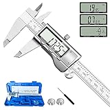
- 【STAINLESS STEEL MATERIAL】The vernier caliper is made of high-strength stainless steel and is waterproof and dirt-proof. The service life of this stainless steel digital caliper is longer than that of calipers with plastic or carbon fiber parts.
- 【ACCURATE MEASUREMENT AND ZERO SETTING】This digital caliper glides smoothly. Measuring range: 0 -6" / 0-150mm; Accuracy: ± 0.001"/ 0.02mm; Resolution: 0. 0005"/0. 01mm. At the same time, the smart design allows you to easily reset to zero by pressing a button and start a new measurement at any point on the scale, which is very suitable for differential measurement.
- 【4 MEASUREMENT MODES】The digital caliper has 4 measurement modes, which can be used to measure inside and outside diameter, depth, and step with two sets of jaws and a probe. Multiple measurement modes can bring more usage scenarios to people, and the measurement process is also very convenient.
- 【UNIT CONVERSION & LARGER LCD SCREEN】These Digital Calipers have a one-key button to quickly switch from inches (inch), fractions (F), millimeters (mm). The 6" digital caliper has a large, easy-to-read LCD DISPLAY which is easy to use and read even under strong sunlight. It will automatically turn off after 5 minutes of non-use to save power.
- 【Wide Applications】 Compared to the ordinary rulers, this stainless steel caliper can measure not only length but also caliber and depth, allows you to measure circular and cylindrical objects, more functions and better performance will satisfy you. It has always been used by professionals and hobbyists alike, jewelers, hobbyists, woodworkers, machinists, DIY, automotive mechanics, and more.
Published figures must also be read in context. For example, Prusa describes 0.2 mm as a general dimensional-accuracy reference for an Original Prusa and suggests at least 0.3 mm as an initial value for movable parts. That is a starting point for testing, not a universal specification for every printer, material, or geometry.
Choose the fit before choosing a number
Start by describing what the interface must do. A removable construction jig may need a loose fit, while a locating bush or drill guide may need a snug fit. A printed cover may need clearance around its perimeter, while a bracket fixed with metal hardware may only need accurately positioned holes.
| Fit type | Intended behavior | Design approach |
|---|---|---|
| Loose clearance | Moves freely with visible play | Use a larger gap for covers, removable parts, and rough field conditions. |
| Sliding | Moves while remaining guided | Use a small, validated gap; surface finish and alignment are important. |
| Locating or snug | Aligns parts accurately but allows separation | Use small clearance and add a lead-in chamfer. |
| Press or interference | Stays together through friction and elastic deformation | Make the pin slightly larger than the hole, then test material, wall thickness, and orientation. |
| Snap fit | Flexes over a retaining feature | Design for controlled deflection, root strength, and cycle life—not just overlap. |
| Print-in-place hinge | Moves without separate assembly | Allow for fused surfaces, support residue, trapped powder, and cleaning access. |
| Threaded | Engages and disengages repeatedly | Use coarse, validated threads and consider a metal insert for repeated use. |
| Sealing | Controls air or fluid leakage | Use an O-ring, gasket, sealant, or machined surface where printed texture is inadequate. |
Formlabs defines clearance as the distance between mating parts and recommends testing the relevant features before committing to a complete assembly.
Clearance: per side or total?
Always state which convention you are using. For a round pin inside a round hole:
hole diameter = pin diameter + total diametral clearance
If the pin is 10.00 mm and the desired total diametral clearance is 0.30 mm, model a 10.30 mm hole.
If 0.20 mm means clearance per side, the hole must be 10.40 mm because the radius increases by 0.20 mm on both sides.
The Tool Desk
Outbyte Driver Updater FREEScan for outdated or missing drivers - takes under a minuteDriver Scan →Outbyte PC Repair FREERepair Windows errors before they cause bigger problemsFix Now →Rank #2

- [INCH/MM Conversion]: One button can quickly convert two measuring unit (INCH/MM). Measuring Range:0 - 150mm (6") / Resolution: 0.01mm (0.0005")/Accuracy: ±0.02mm (0.001")
- [Stainless Steel Material]: The vernier caliper is made of high-strength stainless steel, which is waterproof, stain-proof and oil-proof. The ergonomic design brings you a comfortable feeling.
- [Large and Clear Display Screen]: Large LCD display gives you a clear reading. The thumb rolling and locking screw provide easy sliding, accurate positioning, and fine adjustment.
- [Multifunctional Use]: The digital micrometer can easily and accurately measure internal, external, height and depth dimensions.
- [Automatically shut off]: When you have no action on the dial caliper, it can automatically shut off after 4 minutes.
For a rectangular sliding fit, increase the receiving slot in each relevant axis. Do not assume the error is identical in X, Y, and Z. Add a lead-in chamfer or taper so a small amount of dimensional variation does not prevent assembly.
A practical rule is to document the convention directly in the model or drawing: 0.30 mm total diametral clearance is unambiguous; 0.30 mm clearance is not.
Starting values by printing process
Use the following values to choose the first test coupon—not to skip validation.
FDM or FFF
For movable FDM parts, a test series of 0.20, 0.30, 0.40, and 0.50 mm total clearance is a useful starting matrix. Prusa specifically recommends at least 0.3 mm as an initial value for movable parts, but the right value depends on the printer, material, feature size, orientation, and post-processing.
FDM holes are frequently undersized or distorted relative to their CAD dimensions. First-layer “elephant’s foot,” over-extrusion, corner bulging, bridging, cooling, moisture, warping, layer height, line width, and wall count can all affect a fit. Stratasys Direct’s FDM guidance likewise treats the recommendations as process-specific design guidance rather than a universal accuracy promise.
Resin, SLA, and DLP
Resin printing can produce smaller gaps, but narrow clearances may close because of overexposure, overcure, washing, post-curing, support marks, trapped resin, or dimensional change during cure. Resin type matters: some parts are rigid, while others are brittle or prone to creep.
Use the resin supplier’s design guide and print a coupon in the final orientation. Forge Labs highlights orientation, layer height, and machine tolerances as factors in SLA assembly performance.
Rank #3

- Precise measurement: Measurement range: 0 - 6''/0 - 150 mm; Resolution: 0.01”/0.1 mm; Accuracy: +/- 0.2 mm/0.01”. Perfect and accurate caliper measuring tool for household/DIY measurement
- 4 measuring modes: This digital caliper can be used to Measure inside and outside diameter, depth and step with two sets of jaws and a probe
- Inch/mm conversion: One button quick switch between two units: inch and millimeter, definitely save your time. The buttons are made of rugged plastic carbon fiber composites, durable and portable
- Zero setting function: The smart design allows you to set zero with an easy touch of a button and start a new measurement at any point of the scale, ideal for differential measuring
- Large LCD screen & auto off: The large and easy-to-read LCD display helps you get precise results quickly and easily, auto shutdown for saving battery after 5 minutes if without operation
SLS and MJF
Powder-bed processes can support nested or integrated assemblies, but powder removal, thermal distortion, surface texture, feature size, build location, and spacing between parts still matter.
What’s actually slowing this PC down?
Pick the symptom - the matching free tool is one click away.
For example, Formlabs’ Fuse 1 guidance lists minimum assembly tolerances of 0.2 mm for features below 20 mm² and 0.4 mm for larger features, with integrated assembly clearances of 0.3 mm and 0.6 mm respectively. It also lists 1.0 mm as minimum and 5.0 mm as recommended spacing between separate parts. These figures apply to that Fuse 1 generation and should not be generalized to every SLS or MJF machine.
Outsourced printing
Use the quoted tolerance and design guide for the specific machine, material, build orientation, and service level. Commercial references such as Protolabs’ process-specific guidelines, Makelab’s design table, and Fathom’s additive guidelines demonstrate why one tolerance chart cannot cover all processes.
Make the tolerance parametric in CAD
Do not manually enlarge individual holes until the assembly happens to fit. Put the design intent in named parameters:
pin_nominal = 10.00 mm
clearance_total = 0.30 mm
hole_diameter = pin_nominal + clearance_total
press_fit_allowance = 0.10 mm
press_hole_diameter = pin_nominal - press_fit_allowance
The press-fit value above is only an example parameter to test; it is not a universal interference recommendation.
Do these 3 things before closing this tab:
1Scan for outdated or missing drivers - takes under a minute2Repair Windows errors before they cause bigger problems3Fix the driver behind crashes, sound loss and screen glitchesKeep the mating dimensions driven by a central parameter table. Create variants for loose, sliding, snug, and press fits, or for different materials and printers. Preserve the nominal geometry and store manufacturing compensation separately.
- Offset only functional faces instead of scaling the whole part.
- Add chamfers or tapers to insertion edges.
- Add fillets at snap-fit roots and loaded corners.
- Provide a relief at the end of a sliding fit.
- Add grooves where dust, powder, or debris could otherwise jam the interface.
- Use slots, shims, or adjustable features where field alignment matters more than absolute printed accuracy.
- Keep standard hardware locations nominal unless they require a deliberate fit adjustment.
Parametric CAD tools such as Autodesk Fusion can make these variants easier to maintain and document.
Rank #4

- Solid stainless steel build – This digital caliper 6 inch resists rust, wear, and corrosion, outlasting plastic models. The sturdy metal body handles daily workshop use without bending. The shockproof case protects your measuring tool from drops and impacts, keeping it safe and ready for each job
- Reliable accuracy with smooth glide – This digital vernier caliper measures 0‑6″ / 0‑150mm with ±0.02mm / 0.001″ accuracy and 0.01mm resolution. The thumb roller glides without sticking, and the locking screw holds your reading steady. From checking 3D print filament and woodworking joints to measuring jewelry and small parts for repairs, you can trust the results
- Four measurement modes in one – Use two jaw pairs and a depth probe for ID, OD, depth, and step measurements. No need to switch digital caliper measuring tool – this versatile dial caliper covers tubing, bores, recesses, and shoulders. Press the zero button anywhere to reset for quick comparative checks. Close and re‑zero before each use to ensure consistent readings
- Metric & Imperial conversion with large LCD – This electronic vernier caliper lets you switch between millimeters and inches with one click. The oversized LCD screen displays crisp, bold numbers that are easy to read at a glance. The wide viewing angle means you can read it clearly without tilting the caliper. Auto‑off powers down after 5 minutes of non‑use to save battery
- Complete kit – ready out of the box – Your package includes the digital micrometer, a sturdy case, two batteries (one spare), a mini screwdriver, and a stainless steel ruler. No extra trips to the store – just open and start working. A practical choice for DIYers, hobbyists, and makers who need reliable measurements at home or in the workshop
Print a feature-specific tolerance coupon
A calibration cube can reveal gross scaling problems, but it does not predict the behavior of a hole, snap, thread, hinge, or sliding slot. Test the actual interface instead.
- Model several variants. Include the real hole and pin, slot, dovetail, snap, thread, or hinge geometry. Use several clearance or interference values.
- Label each variant. Emboss or engrave the value into the coupon so the parts cannot be confused.
- Use the final process. Print with the same material, nozzle or layer height, orientation, supports, and slicer settings intended for the part.
- Post-process identically. Remove supports, wash and cure resin, deburr FDM edges, or remove powder exactly as planned for production.
- Measure the result. Record both the printed feature and the mating component.
- Test the actual behavior. Check insertion force, sliding feel, retention, play, alignment, and whether the interface remains usable after repeated operation.
- Update the parameter. Select the smallest gap that reliably performs the required function under expected conditions, not merely the tightest gap that worked once.
- Print the complete part. Confirm the larger geometry because warping, part size, and orientation can introduce additional error.
For a construction jig, the coupon should reproduce the working hole, guide, or locating face—not just a generic test feature.
Measure holes and pins correctly
Measurement tells you whether a problem is a process error, a feature-specific error, or simply an unsuitable fit choice.
- Caliper outside jaws can measure pins reasonably well, but small internal holes are harder to measure accurately with inside jaws.
- Measure at the functional depth, not only at the mouth of the hole.
- Check for elephant’s foot, chamfering, rounded openings, support marks, and ovality.
- Measure several locations around a circular feature.
- Use gauge pins, a bore gauge, telescoping gauge, micrometer, or carefully selected drill bits as go/no-go gauges when the interface is tighter than ordinary calipers can verify.
- Measure multiple printed parts if interchangeability matters. One successful print does not establish repeatability.
Fusion’s manual-inspection workflow describes comparing measured holes, bosses, distances, and other features against nominal dimensions and tolerance limits.
Correct the process before distorting the design
Use the pattern of the error to decide where to intervene.
| Observed result | Likely action |
|---|---|
| Most dimensions are wrong in the same direction | Check printer scaling, extrusion flow, resin exposure, material condition, thermal environment, and slicer settings. |
| Only holes are consistently undersized | Check hole compensation, line placement, orientation, and local geometry. |
| Only the first layer is too tight | Correct elephant’s foot or first-layer squish; do not enlarge every hole in the model. |
| Support-marked faces interfere | Move supports, reorient the part, add a controlled finishing allowance, or machine the face. |
| Parts fit once but later jam | Investigate thermal expansion, resin cure, contamination, powder residue, moisture, creep, and insufficient clearance. |
| A press fit cracks the part | Reduce interference, increase wall thickness, change orientation, add a lead-in, or redesign the load path. |
A global error should normally be corrected in the process. A feature-specific error may justify local CAD compensation. A fit-specific requirement requires intentional clearance or interference. A post-processing requirement needs material reserved for reaming, sanding, drilling, or machining.
Recommended Free Tools
Orientation is part of the tolerance specification
The same CAD dimension can behave differently depending on its orientation.
Best Value

- Best Cost-effectiveness: We've crafted this plastic digital caliper with a singular focus – delivering unmatched value at an unbeatable price. While others chase high-precision innovations, we prioritize essential features that truly matter.
- 4 Measurement Modes and Precision: Outside diameter, inside diameter, depth, and step measurements. Measurement range: 0-6 inches / 0-150 mm, accuracy: ±0.2 mm / 0.01 inches. Whether it's for home projects, DIY, or 3D print, having this caliper will elevate you to be a measurement star.
- Low Energy Consumption Design with Smart Auto-Off Function: With just a single battery, our caliper can support 8+ months of measurements. It can automatically turns on when you slide it, and turns off within 5 mins when not in use, effectively conserving battery power.
- Tough Plastic Case Packaging and Secure Measurements: The plastic case packaging effectively protects the caliper from external impacts and friction, ensuring that it stays in optimal condition at all times. Moreover, our digital caliper is made of extra strong carbon fiber composites that are not easy to damage the measured object during use.
- What You Get: Digital Caliper *1, Tough Plastic Case *1, and LR44 button batteries *3(with one pre-installed). Additionally, we offer a lifetime warranty and friendly customer service to ensure your complete satisfaction.
- Holes in the XY plane may differ from holes aligned with the Z axis.
- Angled cylinders show layer stepping.
- Layer seams can cross a mating surface.
- Supports can scar a functional face.
- Thermal contraction may differ by axis.
- Load direction relative to layer adhesion affects press fits and snap fits.
For a pin or guide, choose orientation based on both surface quality and strength. A smooth-looking surface is not enough if the part can split along layer lines under insertion force. Record the orientation in the project documentation alongside material, nozzle or layer height, slicer profile, post-processing, and target fit.
Special cases
Press fits
A press fit depends on material elasticity, wall thickness, pin texture, insertion force, temperature, long-term creep, and layer direction. Use a gradual interference series rather than one aggressive value. Avoid press-fitting brittle resin parts unless the material and geometry have been validated.
Snap fits
A snap fit must accommodate deflection without exceeding the material’s strain or fatigue limits. Use a longer flexible arm, a generous root radius, and a controlled retaining feature. Check the number of expected cycles and orient the layers so the snap does not peel apart during flexing.
PC Slower Than It Used to Be?
A free scan shows the junk files, broken settings and background clutter dragging Windows down - then fixes them in one click.Free scan · Windows 10 & 11Crashes, No Sound, or Screen Glitches?
Random freezes, missing sound and display glitches usually trace back to one bad driver. Find and replace yours safely.Free scan · under a minutePrinted threads
Coarse threads are more forgiving than fine, machined-thread geometry. Internal threads can retain resin or powder, and external and internal threads may require different compensation. Test a sacrificial thread before printing the final assembly. For repeated service, consider a metal nut, threaded insert, or heat-set insert.
Print-in-place mechanisms
Provide enough clearance for fused surfaces, support residue, powder, and cleaning tools. Include escape paths and access for removing trapped material. A print-in-place hinge that works on the printer but cannot be cleaned is not a successful design.
Bearings, shafts, and inserts
Use printed geometry to locate hardware, not necessarily to replace wear-resistant surfaces. Metal shafts, bushings, captive nuts, washers, and heat-set inserts can provide better service life and repeatability than a printed sliding surface.
Seals
Do not rely on raw printed surfaces for critical sealing. Use a gasket, O-ring, sealant, or a machined sealing face, and provide enough compression and retention for the service conditions.
Quick wins for a faster PC:
Scan for outdated or missing drivers - takes under a minuteDriver Scan →Clear out junk files and repair common Windows errorsFree Scan →When printing is not the right process
If the printed tolerance cannot meet the function reliably, the answer may not be a tighter CAD value. Ream or drill the hole after printing, print oversize and machine the interface, add a metal bushing or insert, use a printed jig with a replaceable wear component, or select a process better suited to the feature.
SLA, SLS, MJF, PolyJet, machining, and outsourced production each have different trade-offs in accuracy, surface finish, strength, cost, and repeatability. A simple construction bracket may be ideal for FDM, while a sealed, load-bearing, or frequently serviced interface may require hardware or a secondary operation.
Practical tolerance checklist
- What must the interface do: move, locate, retain, seal, or transfer load?
- Is the intended fit loose, sliding, snug, press, snap, threaded, or permanent?
- Is clearance stated as per-side or total?
- Which process, material, printer, nozzle, layer height, and orientation will be used?
- Have first-layer, support, warping, curing, powder, and post-processing effects been considered?
- Are the fit dimensions controlled by named CAD parameters?
- Has the actual feature been tested in a small coupon?
- Were the coupon and final part post-processed in the same way?
- Were both mating components measured?
- Does the design require a bushing, insert, gasket, machining, or a different process?
- For repeat production, have several parts been measured to establish repeatability?
A useful project record is: material and supplier; printer or service; nozzle or layer height; slicer or exposure profile; orientation; supports; post-processing; nominal dimensions; clearance convention; target fit; measured range; and acceptance criteria.
Quick Recap
Product prices and availability are accurate as of the date/time indicated and are subject to change. Any price and availability information displayed on Amazon at the time of purchase will apply.