Choose the heat exchanger and controls as one engineered energy-transfer-station (ETS) package, not as separate catalogue purchases. Begin with the district-cooling provider’s connection conditions and the building’s calculated duty. Then select an exchanger that meets both circuits’ temperatures, pressures, flow rates and allowable pressure drops, and design a control sequence that maintains the customer-side supply condition while protecting the network and responding to part-load demand.
A plate-and-frame heat exchanger is a common indirect arrangement, but it is only a starting configuration. The plate construction, connections, ratings, area, staging, valves, sensors, meters, pumps and fail-safe actions must be checked against the serving utility’s current requirements, local codes and the actual building hydraulics. The information below is a design method and specification checklist; it cannot produce a final plate count, valve size or pump setpoint without project data.
As an Amazon Associate I earn from qualifying purchases.
1. Establish the design basis before selecting equipment
The first deliverable should be a written design basis agreed with the district-cooling provider. Heat-exchanger duty is not defined by the building peak load alone: it depends on the temperatures and pressure envelope available on the district side, the temperatures required by the customer side and the hydraulic limits of both systems. The IDEA district-energy guide identifies temperature, differential-pressure and pressure-rating requirements as fundamental selection criteria.
Free tools Windows power users keep installed
One-click scans. No signup required.
Information to obtain from the provider
- Design and operating district supply and return temperatures, including expected variation over the year.
- Available and maximum differential pressure at the connection, plus minimum pressure needed for control at low load.
- Design pressure and temperature ratings, connection standards and any approved materials or equipment lists.
- Required metering arrangement, ownership boundary, communications interface and access for utility operators.
- Rules for isolation, bypasses, redundancy, valve fail position, testing and commissioning.
- Current technical specification and any jurisdiction-specific connection guideline that supersedes older practice.
Information to calculate on the customer side
- Peak and diversified cooling load, seasonal load profile and expected minimum load.
- Customer supply and return temperatures at design and part-load conditions, including coil or process requirements.
- Available pump head, control-valve authority, system volume and the allowable pressure drop through the ETS.
- Design pressure, operating temperature, water quality, fouling risk and maintenance access in the proposed ETS room.
- Whether one exchanger can be taken out of service without interrupting critical cooling, and how a temporary connection would be made if required.
Record every value with its source, date, units and operating case. A provider’s normal temperature is not automatically its design temperature, and a building’s peak load is not necessarily the exchanger’s only sizing point. The final schedule should show design, maximum, minimum and turndown cases rather than a single nominal number.
#1 Best Overall

- 【Premium Quality】Our plate heat exchanger is made of high quality 316L stainless steel which are brazed together by 99.9% copper at the edges for a reliable and rugged part to form a durable, integral piece that can resist leakage and withstand high pressure and temperature.
- 【Convenient For Use And Energy Saving】Smooth Thread makes a easy, quick, flexible hookup. Highly conductive and super-thin stainless steel plates make good performance and economy for heating transfer and cooling without electricity consumption and oxygen consumption.
- 【Product Parameter】250,000 - 330,000 BTU CAPACITY: Depending on the application, this product can produce 250kBtu to 330kBtu per hour. 30 PLATES; 4"x 12", 1" MPT: 30 brazed plates work to efficiently heat water for your application.
- 【Multiple Applications】AB water heat exchanger offers the highest level of thermal efficiency and durability in a compact & lightweight unit, perfect for domestic water heating, Floor Heating, Snow Melting, District or Zone Heating Systems, Outdoor Wood Furnaces, Hydraulic and Lube Oil Coolers, Radiator Heating, Hydronic Heating, Solar Heating, Wood Boiler.
- 【Product Support】 Quality-focused manufacturing backed by responsive support for product questions, selection and installation guidance.
2. Select the exchanger arrangement and configuration
Why an indirect plate-and-frame exchanger is often considered
A plate-and-frame heat exchanger is a typical indirect ETS component: the district water transfers heat to the customer circuit without mixing. Its compactness and separable construction can suit a connection room, but those advantages do not make every plate-and-frame unit interchangeable. The selected unit still needs a thermal and hydraulic rating at the specified temperatures, pressures, flow rates and water conditions.
Configuration decisions that require project review
- Thermal duty: Verify capacity at the provider’s design case and at expected part load. Check that the exchanger can deliver the customer supply temperature when the district-side temperature or differential pressure is at its limiting value.
- Approach temperature: Define the temperature difference between the two circuits at the relevant exchanger end. A closer approach may help achieve a customer supply-temperature target, but it generally requires more heat-transfer surface, increasing equipment cost, footprint and potentially pressure loss. Compare lifecycle consequences instead of applying a universal approach target.
- Pressure drop: Set an allowable drop separately for the district and customer sides. The district value must satisfy the provider’s hydraulic envelope; the customer value must fit pump capability, balancing and control-valve authority. No single pressure-drop limit applies to every connection.
- Design pressure and temperature: Rate plates, frames, gaskets, nozzles and connections for the applicable design cases, including transients identified by the provider. Do not infer a rating from normal operating pressure.
- Materials and water compatibility: Obtain the utility’s approved materials and water-quality requirements before choosing plate and gasket construction. The available information does not establish a universally correct material or gasket.
- Fouling allowance and cleanability: Include the expected water condition and a practical cleaning method in the specification. State how performance will be verified after cleaning and how the unit can be isolated.
- Connections and maintainability: Coordinate nozzle orientation, removable clearance, lifting access, isolation valves, drains, vents and safe working space with the ETS room layout.
- Staging and redundancy: Decide whether one large exchanger, multiple staged units or a duty/standby arrangement best matches load variation, resilience and maintenance requirements.
Compare candidates on the same duty cases
| Selection axis | What to compare | What must be confirmed |
|---|---|---|
| Capacity | Heat-transfer duty at design, maximum and minimum expected loads | Provider and customer temperatures, flow rates and water properties |
| Approach | Closer approach versus surface area, cost, footprint and supply-temperature margin | Customer requirement and district operating strategy |
| Hydraulics | Pressure drop on each circuit at each case | Provider differential-pressure limits and customer pump head |
| Ratings | Design pressure and temperature for plates, frame, gaskets and connections | Utility and code requirements, including transient conditions |
| Maintenance | Fouling tolerance, isolation, cleaning access and replacement method | ETS room access and operator procedures |
| Availability | Single unit, staged units or duty/standby arrangement | Critical-load needs and provider-approved configuration |
| Interface | Metering, sensors, valves, controls and communications | Provider’s approved equipment and operating sequence |
3. Treat approach temperature as a system tradeoff
The approach is not merely a heat-exchanger catalogue number. It links the customer’s required supply temperature to the district-side temperatures and determines how much surface area is needed. Reducing the approach can create useful temperature margin, but the exchanger becomes larger or more expensive and may impose additional pressure drop. A larger approach can reduce first cost and footprint, yet leave insufficient temperature margin when district conditions deteriorate.
Evaluate at least these cases:
- Provider design supply and return temperatures with the building at peak duty.
- Provider minimum or least-favourable supply condition with the building still requiring its specified supply temperature.
- Part-load operation, when control valves may operate near their low-flow limit.
- Any seasonal or reset condition stated by the utility.
Document the chosen approach for each circuit end, the resulting area and pressure drop, and the reason the choice is acceptable to both the provider and the building operator. The 2008 IDEA guide explains the area-and-cost consequence of changing approach, but it does not prescribe one value for every project.
4. Set pressure-drop and pressure-rating requirements with the hydraulic system
Specify pressure drop as a coordinated system constraint. If the exchanger consumes too much district-side differential pressure, the provider may lose control authority or fail to meet service conditions elsewhere in the network. If it consumes too much customer-side head, pumps may run at higher speed, remote coils may become difficult to balance or the control valve may lack authority.
Include these hydraulic checks
- Obtain the provider’s available differential-pressure range at the connection, not just a nominal value.
- Calculate exchanger pressure drop at design flow, maximum flow and the minimum stable flow expected from the control strategy.
- Add the pressure losses of strainers, isolation valves, control valves, meters, fittings and connecting pipework on both circuits.
- Check pump operating points and variable-speed range against the resulting system curve.
- Verify that the selected control valve can regulate over the required turndown without excessive noise, cavitation risk or loss of authority.
- Confirm design pressure ratings for every pressure boundary and identify any relief or protection required by code or the provider.
The available guidance establishes pressure drop and pressure rating as selection criteria but does not establish a universal pressure-drop cap. Put the agreed limits in the equipment schedule and have the provider approve them.
Rank #2

- High-Quality Materials: Made of 316L stainless steel with 99% copper brazing at edges and contact points, forming a robust and leak-resistant unit that withstands high pressure and temperature. UL and CE certified for reliable quality.
- Efficient Heat Transfer: The high-conductivity stainless steel plates feature an asymmetrical herringbone pattern, creating intense pressure turbulence for efficient heating/cooling. With up to 99% heat efficiency, it generates 780-1080K BTU per hour, saving pump power and electricity, reducing overall application costs.
- Large Heat Exchange Area: The heat exchanger features 5”x12” plates with up to 80 plates, providing excellent heat transfer performance for maximum efficiency. Suitable for operating temperatures from -292℉ to 392℉.
- Tight and Leak-Proof: To eliminate the possibility of micro-leaks, the heat exchanger uses high-pressure vacuum brazing and undergoes helium leak testing, ensuring long life and high reliability.
- Stable Installation: Includes two stainless steel brackets made of 304 stainless steel, offering excellent rust resistance and stability for easy and secure mounting of the heat exchanger.
5. Design the control concept around explicit objectives
Controls should state what is being controlled, where it is measured, how the actuator responds and what happens at low load, shutoff, sensor failure and loss of communications. Common objectives are maintaining customer-side supply temperature, limiting or regulating district-side flow, maintaining customer differential pressure and staging exchangers to match demand.
Primary-side flow control for customer supply temperature
One practical arrangement regulates a motorized district-side valve to meet a customer-side supply-temperature setpoint. A 2022 article describing a Gothenburg system uses this strategy while demand-controlling customer-side pumps. The arrangement is a case example, not a universal sequence: valve sizing, sensor location, setpoint reset and limits must be agreed for the actual connection.
Secondary pump control from differential pressure
Where the customer circuit is variable flow, pump speed can respond to differential pressure. The Electrical and Mechanical Services Department’s Hong Kong Technical Guidelines for Connection to District Cooling System, May 2020 edition, states: “Consumer side chilled water pumps shall be controlled based on the differential pressure transmitters (DPT) installed at the consumer’s side of the chilled water system.” The same guideline calls for measurement at the hydraulically far end when the consumer circuit serves more than one building and describes variable-flow pumps controlled from those inputs. These are Hong Kong requirements; they should not be presented as a global rule.
Pressure-independent control valves
The Bureau of Energy Efficiency (BEE) guidelines list pressure-independent control valves among ETS equipment categories. Such valves can be considered where changing differential pressure would otherwise disturb flow control, but the selected valve still needs a project-specific authority, rangeability, actuator, fail position and provider approval. The BEE list also identifies PLCs, temperature and differential-pressure transmitters, and flow or energy meters as ETS equipment categories.
6. Define sensors, meters and the control-panel interface
Provide an instrument schedule that identifies each measurement point, range, accuracy, signal type, power supply, calibration method and alarm. At minimum, coordinate temperatures and differential pressures on both circuits, flow or energy metering where required, valve position, pump status and exchanger availability.
Rank #3
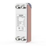
- Excellent Quality: This brazed plate heat exchanger is made of high-quality SS316L stainless steel, brazed with copper in a vacuum environment, ensuring a reliable and robust component. It offers superior resistance to high temperatures, high pressures, corrosion, and leaks, playing an excellent role in supporting various refrigeration, heating, high-temperature, and high-pressure industrial fields.
- Heat-transfer Efficiency increased by 99%: The heat exchanger adopts a fishbone corrugated design, which increases the intensity of the turbulence and creates various support points that reduce the secondary side pressure, resulting in a rapid increase in channel heat transfer efficiency by 99%.
- Convenient to Use and Energy Saving: The smooth threads allow for quick and flexible disassembly and installation. Ultra-thin stainless steel plates provide excellent performance and economy in heating and cooling, improving energy efficiency and reducing operating expenses.
- Product Parameter:Mode WHE4X12-20P can produce up to 275000 btu per hour depending on different applications, 5.6 sq.ft heat transfer area,4"x12"-20 plates with 1"MPT.
- One-year limited warranty: The stainless steel heat exchanger provides exceptional thermal efficiency and durability in a compact, lightweight design and ALORAIR offers a one-year limited warranty covering manufacturing defects.
Sensor-location decisions
- Place customer supply-temperature measurement where it represents the temperature delivered to the building system, not merely the temperature immediately leaving a fitting.
- Locate differential-pressure transmitters at the control point that represents the hydraulically critical circuit. For multi-building customer systems, the Hong Kong guideline specifies the far-end location for its jurisdiction.
- Coordinate flow and energy-meter components with the provider’s ownership and billing boundary.
- Provide isolation, test points and access so transmitters can be calibrated without draining the entire system where the provider permits it.
PLC and operator functions
The PLC or approved controller should expose setpoints, measured values, valve position, pump speed, exchanger stage, meter status, sensor faults and alarms to the agreed operator interface. Define which commands belong to the building operator and which are reserved for the district utility. Include time delays and permissives so a pump cannot run against a closed path and a district valve cannot open before the customer circuit is ready.
Recommended Free Tools
7. Build the operating sequence, including shutoff and staging
Normal start
- Confirm that the customer-side circuit is available, valves are in the permitted position and the selected pump has a run command.
- Start the required customer-side pump and prove flow or differential pressure.
- Open the district-side modulating valve under a controlled ramp.
- Regulate the valve to the agreed customer supply-temperature target while observing flow, differential pressure and high/low limits.
- Enable additional exchanger stages only when the first stage reaches its defined load or control limit and the hydraulic conditions remain acceptable.
Low load and shutoff
The Hong Kong EMSD guideline describes closing the district-side modulating valve when the consumer-side valve is fully closed. It also describes an ON/OFF motorized valve to stage exchanger operation according to instantaneous demand and consumer-side flow. Treat this as a jurisdiction-specific example. Your sequence should state the exact permissive, close delay, minimum-flow protection and restart logic required by the provider.
Fault and maintenance modes
- On loss of a critical temperature or pressure signal, move valves to the provider-approved fail position and generate a clear alarm.
- On loss of customer flow, prevent or close district flow to avoid uncontrolled heat transfer and unnecessary pumping.
- On high differential pressure, high temperature or other defined limit, protect the exchanger and notify the operator.
- Permit isolation of one exchanger or pump for maintenance if redundancy is provided, and record the reduced-capacity operating mode.
- Define manual override authority, timeout and return-to-automatic behaviour so a temporary override cannot remain unnoticed.
8. Compare control schemes before committing to hardware
| Control scheme | Controlled variable | Typical equipment involved | Questions to resolve |
|---|---|---|---|
| Temperature-led primary flow | Customer-side supply temperature | Primary motorized valve, supply-temperature sensor, controller | Setpoint, reset, valve authority, low-load stability and fail position |
| Customer differential-pressure pump control | Customer-side differential pressure | Variable-speed pumps, DPTs, pump controller | Sensor location, minimum speed, far-end pressure requirement and multi-building hydraulics |
| Pressure-independent flow control | Commanded flow or temperature with pressure compensation in the valve | Pressure-independent control valve, actuator and controller | Approved valve range, pressure range, metering and maintenance |
| Staged exchanger operation | Demand, flow or capacity threshold | Multiple exchangers, isolation or ON/OFF valves, PLC | Stage thresholds, equal runtime, minimum run time and standby strategy |
Many ETS designs combine these functions: pumps respond to customer differential pressure, a primary valve responds to customer supply temperature and the PLC stages exchangers. The combination is not automatically correct; tune each loop so that pump and valve actions do not fight one another.
Independent reader supportYour contribution helps us test, update, and keep practical guides available for everyone.9. Use the published examples without treating them as universal settings
The Gothenburg case study published in 2022 describes a local design context with 8 °C secondary supply, 18 °C secondary return, 6 °C primary supply, 16 °C primary return and a 2 °C approach. Those figures reflect Swedish guidance for the studied system. They are useful for understanding how primary and secondary temperatures relate, but they are not a general district-cooling standard and should not be copied into another project without a provider-approved design basis.
Likewise, the EMSD May 2020 sequence and the BEE equipment categories demonstrate the kinds of pump, valve, sensor, PLC and metering functions that may appear in an ETS. Hong Kong and India requirements are jurisdiction-specific, while the 2008 IDEA guide is foundational practice rather than a substitute for the serving utility’s current specification.
PC Slower Than It Used to Be?
A free scan shows the junk files, broken settings and background clutter dragging Windows down - then fixes them in one click.Free scan · Windows 10 & 11Outdated Drivers Are Slowing You Down
One free scan finds every outdated or missing driver and matches the right update for your exact hardware.Free scan · exact hardware matchRank #4

- High-Quality Materials: Made of 316L stainless steel with 99% copper brazing at edges and contact points, forming a robust and leak-resistant unit that withstands high pressure and temperature. UL and CE certified for reliable quality.
- Efficient Heat Transfer: The high-conductivity stainless steel plates feature an asymmetrical herringbone pattern, creating intense pressure turbulence for efficient heating/cooling. With up to 99% heat efficiency, it generates 260-360K BTU per hour, saving pump power and electricity, reducing overall application costs.
- Large Heat Exchange Area: The heat exchanger features 5”x12” plates with up to 30 plates, providing excellent heat transfer performance for maximum efficiency. Suitable for operating temperatures from -292℉ to 392℉.
- Tight and Leak-Proof: To eliminate the possibility of micro-leaks, the heat exchanger uses high-pressure vacuum brazing and undergoes helium leak testing, ensuring long life and high reliability.
- Stable Installation: Includes two stainless steel brackets made of 304 stainless steel, offering excellent rust resistance and stability for easy and secure mounting of the heat exchanger.
10. Specify staging, redundancy and maintenance deliberately
Decide what happens when an exchanger, pump, valve, sensor or controller is unavailable. A single large exchanger may have a smaller footprint, while staged units can improve part-load matching and permit maintenance with reduced capacity. Duty/standby equipment can protect critical loads but adds valves, controls, space and commissioning effort. The right arrangement depends on the building’s criticality, provider rules, available room and cost of interruption.
Questions for the design review
- What percentage of required load must remain available with one exchanger or pump isolated?
- Can the provider permit a bypass, temporary connection or reduced-flow operating mode?
- Are isolation valves, drains, vents and lifting paths accessible without shutting down unrelated systems?
- How will equal runtime, automatic changeover and alarm acknowledgement be handled?
- What performance test proves that each stage delivers its scheduled duty and pressure drop?
11. Commission the complete ETS, not just the exchanger
- Verify installed equipment, materials, pressure ratings, flow direction, access clearances and identification against approved drawings and schedules.
- Flush, clean, fill, vent and pressure-test each circuit according to the provider and code requirements.
- Calibrate temperature, differential-pressure and flow or energy meters; record certificates and as-left values.
- Prove pump rotation, variable-speed range, valve stroke, fail position, interlocks and communications.
- Test normal start, temperature control, differential-pressure control, staging, shutoff, sensor failure, loss of flow and loss of power.
- Measure temperatures, flows, differential pressures and valve positions at several loads, including the lowest stable load.
- Compare results with the approved design cases and obtain provider acceptance before placing the ETS in normal operation.
Commissioning should also leave operators with a sequence-of-operation document, alarm matrix, setpoint list, meter ownership statement, maintenance instructions and a record of approved overrides.
12. Common selection mistakes and how to avoid them
- Ordering from peak load alone: Require design and part-load checks using provider and customer temperatures and flows.
- Choosing a generic plate-and-frame unit: Make the manufacturer demonstrate duty, approach, pressure drop, ratings and cleanability for the specified cases.
- Setting a universal approach temperature: Show the area, cost, footprint and supply-temperature consequences of the selected approach.
- Ignoring the district differential-pressure envelope: Check the complete primary-side loss, including valves, strainers, meters and pipework.
- Putting the DPT in a convenient rather than critical location: Locate it where the hydraulic design requires; the Hong Kong guideline uses the far end for a multi-building consumer circuit.
- Letting pump and valve loops compete: Assign one clear objective to each loop, define permissives and tune them together.
- Copying another jurisdiction’s sequence: Treat EMSD, BEE and Swedish examples as references and secure local provider approval.
- Leaving maintenance out of the room layout: Reserve removal, cleaning, isolation, draining and lifting space before equipment is ordered.
- Failing to define low-load behaviour: State minimum flow, valve closure, stage thresholds, delays and restart conditions.
13. A specification package the provider can review
Submit one coordinated package rather than separate exchanger and controls documents. It should contain:
- Design-basis report with load cases, temperatures, flows, pressure envelope and allowable pressure drops.
- Exchanger schedule showing duty, approach, pressure drop, design pressure and temperature, materials, connections, fouling allowance, dimensions and maintenance clearances.
- Hydraulic calculations for both circuits, including pump curves and control-valve authority.
- Piping and instrumentation diagram with isolation, strainers, drains, vents, meters, sensors, valves and flow direction.
- Control narrative covering normal operation, start, stop, staging, low load, faults, maintenance and manual override.
- Instrument and point schedule with ranges, accuracy, locations, calibration and communications.
- Equipment data sheets and evidence of compliance with provider-approved materials and interfaces.
- Testing and commissioning plan with acceptance criteria for capacity, temperatures, flow, differential pressure, alarms and fail-safe actions.
Ask the utility to confirm the current connection conditions before procurement. The 2008 IDEA guidance, Hong Kong’s May 2020 EMSD guideline, BEE guidance and the 2022 Gothenburg case study provide useful reference points, but none can replace the serving provider’s project-specific approval.
Quick wins for a faster PC:
Fix the driver behind crashes, sound loss and screen glitchesFind Drivers →Repair Windows errors before they cause bigger problemsFix Now →Quick Recap
Product prices and availability are accurate as of the date/time indicated and are subject to change. Any price and availability information displayed on Amazon at the time of purchase will apply.

