Do these 3 things before closing this tab:
1Clear out junk files and repair common Windows errors2Scan for outdated or missing drivers - takes under a minute3Repair Windows errors before they cause bigger problemsBuilding your own mini energy generator with magnets demonstrates electromagnetic induction: a hand crank rotates permanent magnets near a fixed copper coil, changing magnetic flux and inducing a voltage. The magnets do not create free energy; the person turning the crank supplies the mechanical energy that becomes a small, variable electrical output.
The most practical beginner arrangement uses a stationary coil, a balanced rotor carrying permanent magnets, and a low-power LED or sensitive multimeter. A moving magnet through a tube or coil is an even simpler first demonstration, but the hand-cranked design is better for controlled experiments.
As an Amazon Associate I earn from qualifying purchases.
Key takeaways
- A mini generator needs relative motion that continually changes magnetic flux through a conductive coil; stationary magnets beside a stationary coil will not produce continuous useful output.
- The crank supplies the mechanical energy, while the magnets provide the magnetic field and the copper winding converts changing flux into electrical voltage.
- Faster motion, more coil turns, stronger magnetic coupling, and a smaller safe air gap can improve the signal, but added wire resistance and friction limit the result.
- A homemade generator is best suited to a sensitive meter, a flashing or glowing LED, or another very small demonstrative load—not household appliances or dependable phone charging.
- Small high-powered magnets can cause fatal internal injuries if swallowed, so magnet containment, eye protection, and low-speed testing are essential.
How does building your own mini energy generator with magnets work?
Building your own mini energy generator with magnets demonstrates electromagnetic induction: a hand crank rotates permanent magnets near a fixed copper coil, changing magnetic flux and inducing a voltage. The magnets do not create free energy; the person turning the crank supplies the mechanical energy that becomes a small, variable electrical output.
Faraday’s law explains the conversion. A changing magnetic flux through a circuit induces an electromotive force. Magnetic flux changes when the magnetic field, the coil’s enclosed area, or the coil’s orientation changes. A rotating magnet therefore produces a changing, usually alternating electrical signal in the winding. The U.S. Department of Energy’s electricity-industry primer describes the full-scale version as turbines rotating magnets around conductive coils to induce alternating currents and voltages; a hand-cranked model uses the same principle at miniature scale.
#1 Best Overall
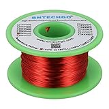
- High Quality enameled Copper Wire!Durable and not break while winding the coils.Highly Efficient!
- Magnet wire is copper wire that coated with a thin layer of insulated enamel.This 28AWG magnet wire is 4 ounces(527 feet).
- This enamelled copper wire the insulation is made from Solderable Polyurethane,and protects the coiled wire from short-circuiting.Temperature rating 155°C (311°F) makes it suitable for several thermal overload applications.Raw copper is drawn to meet specific size requirements based on NEMA MW-79-C standard.
- 28 gauge enameled magnet wire: Wrapped in spool and color is red.Outside diameter 0.0122"for perfect thickness.
- BNTECHGO magnetic copper wire is widely used in the construction of transformers,wound coils,motors,solenoids,instruments,inductors,speakers,electromagnets,and other applications that require tight coils of insulated wire.
In the recommended arrangement, the hand crank replaces the turbine, permanent magnets provide the magnetic field, the copper coil is the conductive circuit, and an LED or meter makes the output visible.
Which mini generator design should you build?
A fixed coil with a rotating magnetic rotor is the most useful beginner design when you want to compare speed, magnet placement, coil turns, and air gap. A moving-magnet tube is simpler and safer to understand initially, but it offers less control over repeated mechanical experiments.
| Design | Construction | Visible result | Best use | Main limitation |
|---|---|---|---|---|
| Hand-cranked rotor | Fixed coil plus magnets secured to a shaft or rotor | LED flashes or glows; meter reading varies with speed | Testing magnet count, coil turns, alignment, core material, and air gap | Requires balanced mechanical parts and secure magnet containment |
| Moving magnet through a coil | Pass a permanent magnet rapidly through a tube or stationary coil | Brief LED flash or meter deflection | First demonstration of changing magnetic flux | Output is intermittent and motion is harder to standardize |
| Rotor with an iron core | Use a suitable soft iron former or core to concentrate flux | Potentially stronger induced signal when alignment is good | Investigating magnetic coupling | The core can increase magnetic pull, friction, or rotor interference |
A documented Science Buddies generator project uses a U-shaped coil and a rotor carrying six neodymium magnets. The same project reports useful results in its experimental setup from one coil and two neodymium magnets positioned 180 degrees apart. Those are features of that documented build, not a universal specification for every homemade generator.
Windows Errors? Fix Them Before They Spread
Repair common Windows errors and clear accumulated junk for a smoother, more stable PC - no reinstall needed.Free scan · no reinstallCrashes, No Sound, or Screen Glitches?
Random freezes, missing sound and display glitches usually trace back to one bad driver. Find and replace yours safely.Free scan · under a minuteWhat materials do you need?
The coil is the essential electrical component. Use insulated or enamelled copper magnet wire so many turns can be wound without adjacent turns electrically shorting together.
Core materials
- Enamelled copper magnet wire
- One or more permanent magnets appropriate for the rotor
- A small shaft, axle, spindle, or hand-crank mechanism
- A rigid frame or nonconductive coil support
- A low-power LED or sensitive multimeter
- Clips, terminals, or soldered connections
For the winding, enameled copper magnet wire is the most direct component to obtain because the thin enamel provides turn-to-turn insulation while the copper carries the induced current. The enamel must be removed from both wire tails before connecting the coil; otherwise, a completed winding can appear electrically dead.
Useful optional parts
- A soft iron core or iron former
- A cardboard or plastic tube for the moving-magnet version
- Small bearings, bushings, or low-friction supports
- Tape, screws, brackets, or a wooden base
- A second coil or rectifier components for later experiments
A complete educational motor-and-generator kit can also be useful for a classroom or structured project because the documented supplier listing includes magnet wire, disc and neodymium magnets, soft iron cores, an LED, hardware, and a project book. Kit contents and availability can change, so verify the current listing before buying.
Rank #2
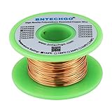
- High Quality enameled Copper Wire!Durable and not break while winding the coils.Highly Efficient!
- Magnet wire is copper wire that coated with a thin layer of insulated enamel.This 22AWG magnet wire is 4 ounces (122 feet).
- This enamelled copper wire the insulation is made from Solderable Polyurethane,and protects the coiled wire from short-circuiting.Temperature rating 155°C (311°F) makes it suitable for several thermal overload applications.Raw copper is drawn to meet specific size requirements based on NEMA MW-79-C standard.
- 22 gauge enameled magnet wire: Wrapped in spool and color is natural.Outside diameter 0.0256"for perfect thickness.
- BNTECHGO magnetic copper wire is widely used in the construction of transformers,wound coils,motors,solenoids,instruments,inductors,speakers,electromagnets,and other applications that require tight coils of insulated wire.
How do you build the hand-cranked generator?
1. Wind the copper coil
Wind many neat, reasonably tight turns around a rigid former, leaving two wire tails for the connections. Keep the winding shape consistent and avoid crushing or sharply bending the wire. More turns generally increase induced voltage because the changing flux links more loops, but more wire also adds resistance; the highest turn count is not automatically the best design for delivering current.
Free tools Windows power users keep installed
One-click scans. No signup required.
Strip the enamel from the ends with an appropriate stripping method, then check that bare copper is exposed. The Department of Energy’s electromagnetic-generator activity uses copper-wire coils and notes that adding coils can help when an initial arrangement produces no visible result.
2. Secure the coil to the frame
Fasten the coil to a nonconductive support so the winding cannot move into the rotor. A loose coil wastes motion, changes the air gap, and can be struck by a magnet. Magnetic attraction can pull components together unexpectedly, particularly when an iron core is added.
3. Assemble and balance the rotor
Attach the magnets symmetrically to a shaft or rotor. Use a mechanically secure holder rather than relying only on a weak adhesive bond, especially at higher speed. Confirm that every magnet is contained, the shaft is aligned, and the rotor turns freely without scraping the coil or frame.
4. Connect an indicator
Connect the two coil ends to a sensitive multimeter or a low-power LED. A meter is usually the better first diagnostic because a small voltage may exist even when an LED fails to light because of polarity, threshold voltage, or a poor connection. The University of Iowa induction demonstration uses coil-and-magnet motion with indicators to make the induced current observable.
The Tool Desk
Outbyte Driver Updater FREEFix the driver behind crashes, sound loss and screen glitchesFind Drivers →Outbyte PC Repair FREEClear out junk files and repair common Windows errorsFree Scan →5. Turn the crank slowly, then increase speed
Begin at low speed while watching the rotor, frame, wiring, and magnet attachments. Increase speed only after the assembly remains stable. Faster movement generally changes magnetic flux more rapidly and produces a stronger observed signal; an Arizona State University spinning-magnet demonstration illustrates this relationship.
Rank #3

- ENAMELED COPPER MAGNET WIRE (18 AWG): This 1 lb spool holds about 202 ft of solid enameled copper magnet wire in 18 gauge - heavy build (Grade 2) insulation for winding and rewinding coils.
- 220°C (428°F) THERMAL CLASS: Dual polyesterimide + polyamide-imide enamel coating withstands high heat, abrasion and solvents, delivering reliable insulation and long service life in demanding jobs.
- MANY USES: Rewind and build electric motors, transformers, generators, solenoids, chokes, inductors, speakers and guitar pickups, electromagnets, Tesla coils and other DIY electronics projects.
- EASY TO WIND & SOLDER: Flexible copper takes tight, even turns; the enamel strips off easily with fine sandpaper, a blade or heat so you can tin and solder clean connections.
- PRECISION-DRAWN & CONSISTENT: Manufactured by Emtel, an established enameled wire producer, with tight diameter tolerance for even windings, predictable resistance and dependable performance.
How can you improve the generator’s output?
Change one variable at a time and record the same meter reading or LED behavior after each change. A controlled comparison is more informative than changing the magnets, winding, speed, and load simultaneously.
| Variable | Likely effect | Trade-off or caution |
|---|---|---|
| Rotor speed | Faster flux changes generally increase the induced signal | Higher speed increases mechanical risk and can eject a poorly secured magnet |
| Number of coil turns | More turns can increase induced voltage | Longer wire adds resistance and may reduce delivered current |
| Magnet strength and pole arrangement | Stronger fields and better placement can improve coupling | Magnets can pull into the core, pinch fingers, or detach from a spinning rotor |
| Air gap | A smaller safe gap usually improves magnetic coupling | The rotor must never strike the coil, core, or frame |
| Coil area and alignment | Consistent alignment can increase the changing flux through the winding | Poor geometry may leave much of the magnetic field outside the active coil area |
| Core material | A suitable soft iron core can concentrate magnetic flux | Magnetic pull and friction may increase, causing stalling or contact |
| Electrical load | A sensitive LED or meter is easier to operate than a demanding load | A filament bulb, motor, or phone charger needs substantially more usable output |
LEDs are generally easier to illuminate than filament bulbs in small induction demonstrations. A simple rotating generator naturally produces alternating output, so an LED may flash, light only during part of a cycle, or fail because its polarity is unsuitable. A rectifier can convert the alternating signal into a one-direction output, but a rectifier does not create additional energy.
Can magnets generate electricity or free energy?
Magnets can enable electricity generation, but magnets do not supply free energy. The generator requires mechanical work from a hand crank, falling mass, wind rotor, water turbine, or another source of motion. The electrical output cannot continuously exceed the mechanical input after friction, electrical resistance, and other losses.
A stationary magnet next to a stationary coil does not continuously generate useful power because the magnetic flux is not changing. Relative motion is essential: the magnet can move through the coil, the coil can move through the magnetic field, or the magnetic field can rotate relative to the coil.
What can a homemade magnet generator power?
A homemade mini generator can produce a visible LED flash or glow, a measurable meter reading, and under favorable conditions possibly enough output for a very small motor or similar demonstration load. Output varies with magnet field, coil dimensions, turns, speed, internal resistance, bearings, wiring, and load, so there is no universal voltage, wattage, runtime, or phone-charging claim for an improvised design.
The appropriate goal is observation and controlled experimentation rather than household power. Do not connect the generator to mains wiring. Do not treat a small prototype as a certified power supply, emergency charger, or safe source for appliances.
Rank #4

- High Quality enameled Copper Wire!Durable and not break while winding the coils.Highly Efficient!
- Magnet wire is copper wire that coated with a thin layer of insulated enamel.This 30AWG magnet wire is 4 ounces(840 feet).
- This enamelled copper wire the insulation is made from Solderable Polyurethane,and protects the coiled wire from short-circuiting.Temperature rating 155°C (311°F) makes it suitable for several thermal overload applications.Raw copper is drawn to meet specific size requirements based on NEMA MW-79-C standard.
- 30 gauge enameled magnet wire: Wrapped in spool and color is red.Outside diameter 0.0098"for perfect thickness.
- BNTECHGO magnetic copper wire is widely used in the construction of transformers,wound coils,motors,solenoids,instruments,inductors,speakers,electromagnets,and other applications that require tight coils of insulated wire.
Why is the homemade generator not producing electricity?
Most apparent failures come from an open circuit, insufficient flux change, poor coupling, an unsuitable indicator, or a mechanical problem. Work through the checks below in order.
| Symptom | Likely cause | Correction |
|---|---|---|
| No light and no meter movement | Enamel remains on the wire ends or a connection is open | Strip both tails, inspect every joint, and check continuity through the coil |
| No visible LED result but the rotor turns | Speed, magnet proximity, coil turns, or LED threshold is inadequate | Turn faster, reduce the safe air gap, add turns, or test with a sensitive meter |
| LED works only in one direction | The LED is polarity-sensitive and the generator output alternates | Reverse the LED leads as a diagnostic or use a suitable rectifier arrangement |
| Rotor stalls | Rubbing, shaft misalignment, excessive magnetic pull, or a flexible frame | Reduce friction, realign the shaft, stiffen the frame, or remove the interfering core |
| Wire becomes hot | A short circuit or excessively demanding load | Stop immediately, disconnect the load, and inspect the winding and connections |
Use continuity testing before changing the mechanical design. If continuity is correct, bring the magnets closer without allowing contact, increase speed cautiously, and use a meter before assuming that no voltage is present. The University of Alaska Fairbanks educational material also demonstrates how magnet motion and coil connections affect the observable electrical response.
Independent reader supportYour contribution helps us test, update, and keep practical guides available for everyone.How do you use magnets and a spinning rotor safely?
High-powered magnets require more care than ordinary craft magnets. According to the U.S. Consumer Product Safety Commission’s September 7, 2022 release, an estimated 26,600 magnet ingestions were treated in hospital emergency rooms from 2010 through 2021, and the CPSC knew of seven deaths involving hazardous magnet ingestion. When two or more magnets are swallowed, they can attract through internal tissue and cause perforation, blockage, infection, blood poisoning, or death.
- Keep loose neodymium magnets away from young children and anyone who may put objects in their mouth.
- Never place magnets in or near the mouth or nose.
- Store magnets so they cannot detach from the rotor or become loose hardware.
- Use eye protection during first spin tests and keep hands, hair, and clothing away from moving parts.
- Watch for sharp stripped wire ends and pinch points between magnets and metal parts.
- Test at low speed before increasing the crank rate.
- Stop immediately if a magnet flies loose, the rotor contacts the frame, or the wire becomes hot.
- If a magnet may have been swallowed, seek immediate medical attention and follow the CPSC magnet-safety guidance.
Containment is part of the design, not an optional finishing touch. A rigid frame, balanced rotor, secure mechanical holders, and a low-speed test reduce the chance that a fast-moving magnet becomes a projectile.
Is a mini magnet generator worth building?
Yes, if the goal is to see electromagnetic induction and investigate how motion, coil turns, magnet arrangement, alignment, and load affect output. A hand-cranked rotor provides the best platform for repeatable comparisons, while a moving magnet through a coil gives the quickest first demonstration. Neither design should be sold as a free-energy machine or a practical household generator.
The strongest experiment is to establish one baseline, then change only one feature: crank speed, number of turns, magnet count, air gap, core material, or indicator. Record meter behavior or LED brightness and explain every result in terms of changing magnetic flux and mechanical energy input.
Best Value

- High Quality enameled Copper Wire!Durable and not break while winding the coils.Highly Efficient!
- Magnet wire is copper wire that coated with a thin layer of insulated enamel.This 20AWG magnet wire is 4 ounces (80 feet).
- This enamelled copper wire the insulation is made from Solderable Polyurethane,and protects the coiled wire from short-circuiting.Temperature rating 155°C (311°F) makes it suitable for several thermal overload applications.Raw copper is drawn to meet specific size requirements based on NEMA MW-79-C standard.
- 20 gauge enameled magnet wire: Wrapped in spool and color is red.Outside diameter 0.0315"for perfect thickness.
- BNTECHGO magnetic copper wire is widely used in the construction of transformers,wound coils,motors,solenoids,instruments,inductors,speakers,electromagnets,and other applications that require tight coils of insulated wire.
Frequently Asked Questions
Can a stationary magnet generate electricity?
A stationary magnet beside a stationary coil will not continuously generate useful electricity because the magnetic flux is not changing. Move the magnet through the coil, rotate magnets near it, or move the coil through the field so the flux changes.
How many coils do you need for a homemade generator?
There is no universal coil count for a homemade generator. More turns can increase induced voltage, but additional wire also increases resistance; compare turn counts experimentally while keeping speed, magnets, geometry, and load consistent.
Can a homemade magnet generator power a phone?
A homemade mini generator should not be expected to charge a phone reliably. Its output varies with speed, coil design, magnets, internal resistance, and load, while the educational examples are intended for LEDs, meters, and other very small loads.
What’s actually slowing this PC down?
Pick the symptom - the matching free tool is one click away.
What should you do if someone swallows a powerful magnet?
If magnets may have been swallowed, seek immediate medical attention. Multiple high-powered magnets can attract through internal tissue and cause perforation, blockage, infection, blood poisoning, or death.
The Bottom Line
A successful mini generator needs three things: a changing magnetic field, an insulated copper coil, and mechanical motion. Build a secure low-speed rotor, use a meter or LED as a small load, compare one design variable at a time, and treat the project as an electromagnetic-induction demonstration—not a source of free or household-scale energy.
Quick Recap
Product prices and availability are accurate as of the date/time indicated and are subject to change. Any price and availability information displayed on Amazon at the time of purchase will apply.

