What’s actually slowing this PC down?
Pick the symptom - the matching free tool is one click away.
For a dependable construction scan, start with about 6 mm point spacing at 10 m for terrestrial laser scanning (TLS), plan at least 10–20% useful-range overlap between adjacent stations, and use 85% forward and 70% side overlap for a drone mapping grid. Establish at least three surveyed ground-control points (GCPs), with five distributed around the site preferred for normal projects. Then verify registration, georeferencing and coverage rather than treating any setting as a guaranteed accuracy value.
The right settings depend on the smallest feature you must measure, the scanner or camera range, line-of-sight obstructions, the tolerance in the deliverable, and the time available for fieldwork and processing. More resolution alone is rarely the best fix for missing coverage or weak registration.
As an Amazon Associate I earn from qualifying purchases.
Quick-start settings for a construction site
Use the following as a planning baseline, then adjust after considering feature size, range, occlusion and the required measurement tolerance.
| Task | Starting setting | When to increase it |
|---|---|---|
| Terrestrial laser scanning | About 6 mm point spacing at 10 m | Use finer spacing for small features, long-range surfaces or tighter-detail deliverables. |
| Adjacent TLS stations | At least 10–20% overlap of useful scanner range | Increase overlap where walls, columns, equipment or terrain cause occlusion, or where registration has few distinctive shared features. |
| Drone photogrammetry, general grid | At least 75% forward and 60% side overlap | Use about 85% forward and 70% side overlap as a stronger construction starting point. |
| Drone interiors or tall structures | About 90% overlap for interiors; high overlap around tall structures | Increase overlap when changing viewpoints and image redundancy are needed to resolve complex geometry. |
| Ground-control points | Minimum three surveyed GCPs; five preferred | Add points for large, irregular or elevation-changing sites, and for areas exceeding 20 acres. |
These figures describe planning targets, not a universal accuracy guarantee. Weather, dust, reflective materials, moving plant, range, scanner model, camera optics and the required tolerance can all force a different choice.
#1 Best Overall
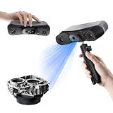
- 【Industrial-Grade Accuracy】Achieve single-frame accuracy up to 0.03 mm and volumetric accuracy of 0.03 mm + 0.05 mm x L(m), faithfully reproducing the finest surface details and complex geometries with exceptional consistency. Full-Field Structured Light accuracy reaches 0.08 mm; VCSEL mode delivers 0.10 mm @ 300-500 mm and 0.20 mm @ 500-800 mm. Engineered to meet the demanding requirements of 3D printing, reverse engineering, and precision modeling applications.
- 【Ultra-Fast Scanning & Robust Frame Rate】Multi-line Laser mode delivers up to 105 fps with NVIDIA GPU acceleration. Full-Field Structured Light mode achieves up to 5,000,000 points/s. The high frame rate ensures a smooth, uninterrupted scanning experience, especially suited for rapidly capturing large objects and complex scenes, significantly boosting overall workflow efficiency.
- 【AI-Powered & Photo-Grade Retopology】 AI object segmentation (Windows only) identifies your target in one click, tracks it throughout the scan, and auto-filters background noise — delivering clean data and streamlining post-processing. The patented 3D Gaussian Splatting converts point cloud and RGB data into true-to-life 1:1 photorealistic models; import photos from your phone or camera to apply real textures, then export in splat format for gaming, animation, and VR.
- 【All-Weather Outdoor Scanning】Multi-line Laser mode operates reliably up to 50,000 lux; with an outdoor filter attached, scanning remains stable in lighting conditions of up to 100,000 lux; VCSEL mode operates reliably in up to 100,000 lux ambient light. Designed to overcome lighting challenges, it provides consistent all-weather performance for construction sites, archaeological digs, and industrial fieldwork.
- 【5 Scanning Modes】NIR band supports Full-Field HD Scanning (markerless, fine structured light), Hybrid HD Scanning (dual projectors, fast high-quality modeling), and VCSEL Rapid Scanning (high-density pattern, fast markerless capture). Blue light band supports 30-Cross Laser Lines Scanning (handles high-reflectivity metals & dark objects) and Single-Line Deep Hole Scanning (captures from deep holes & narrow grooves). Five modes for comprehensive indoor and outdoor coverage.
How to set terrestrial laser scanner resolution
Understand point spacing at the working range
Scanner resolution is commonly expressed as point spacing at a stated distance. A setting that produces 6 mm spacing at 10 m does not produce 6 mm spacing at every range: spacing grows as the surface gets farther from the instrument. Record the distance used in the specification and compare it with the actual range to the feature you need to measure.
For general construction documentation, begin near 6 mm point spacing at 10 m. Trimble’s current manufacturer table lists these examples:
| Trimble mode | Point spacing at 10 m | Practical implication |
|---|---|---|
| High | 6.3 mm | General documentation baseline |
| High x2 | 3.1 mm | Finer detail with more points, storage and scan time |
| High x4 | 1.6 mm | Very fine sampling with the greatest field and processing cost |
The table is a manufacturer specification at 10 m, not a statement that every measured dimension will be accurate to the listed spacing. Accuracy also depends on the instrument, incidence angle, registration, surface quality and how the point cloud is interpreted.
The Tool Desk
Outbyte PC Repair FREERepair Windows errors before they cause bigger problemsFix Now →Outbyte Driver Updater FREEFix the driver behind crashes, sound loss and screen glitchesFind Drivers →Match spacing to the smallest feature
Choose a spacing that gives several points across the feature you need to identify. A small bolt, narrow joint or thin edge viewed from a long distance may disappear at a coarse setting even though large walls look complete. Conversely, scanning a broad, flat slab at an unnecessarily fine setting can multiply files and processing time without adding useful information.
- Use the baseline setting when the deliverable is general progress documentation, coordination or as-built context and most surfaces are within roughly the planned working range.
- Move to a finer mode when a feature is small relative to range, when a long-range surface must be measured, or when the specification calls for tighter detail.
- Keep the finer mode local where possible. High-detail scans of every station can create large datasets even when only a few locations need them.
Prefer useful viewpoints over maximum resolution everywhere
Trimble notes that a greater number of lower-resolution scans will often provide better overall coverage than fewer high-resolution scans because additional viewpoints capture more surfaces and create more overlap for registration. This matters on active sites: a column, temporary wall, stored material or piece of plant can hide a critical area from one station. Moving the scanner to another position may recover that geometry more effectively than increasing the first station’s resolution.
A practical plan is to use the baseline resolution for a network of well-placed stations, then add targeted high-resolution scans where the model, inspection or measurement requires them. Before leaving a setup, inspect the live view or preview for shadowed corners, undersides, penetrations and narrow spaces.
Plan overlap between terrestrial scan stations
Use 10–20% useful-range overlap as a field baseline
The New Jersey Department of Transportation’s 2014 survey manual gives at least 10–20% overlap of useful scanner range between adjacent terrestrial stations as a planning baseline. “Useful” means the portion of the scan that contains reliable, shared geometry—not empty sky, a highly reflective patch or a temporary object that may move before the next station.
Overlap is not the same as distance between tripods. Two stations can be close yet share little usable geometry if a wall blocks the view. Conversely, stations farther apart can register well when they see the same planes, corners or targets from different angles.
Rank #2
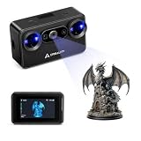
- Pocket-Sized & Wireless Freedom: At only 260g and 1006035mm, Pika fits in your palm. Features Wi-Fi 6 wireless PC mode, 3-inch HD touchscreen (500 nit), dual swappable 3350mAh batteries for extended sessions, and supports outdoor scanning up to 110,000 lux - scan anywhere, anytime without cables
- Dual-Mode Scanning with Blue Laser & NIR Structured Light: Switch between 7-line blue laser mode for fine detail capture and NIR structured light mode for full-body scanning with 24-bit true color. Scan objects from 101010mm to 200020002000mm - from tiny miniatures to life-size body scans - all with one device
- Ultra-High Precision 0.03mm Accuracy: Equipped with 7 parallel blue laser lines, Creality Pika delivers up to 0.03mm scanning accuracy and 0.1mm 3D resolution, capturing intricate details on small parts, figurines, mechanical components, and collectibles with professional-grade precision for 3D printing and reverse engineering
- AI-Powered Smart Features: Built-in AI Body Completion generates full-body 3D models from just a face scan and photos in as little as 10 seconds (10 faster). AI Retexturing maps real photo textures onto scanned models for lifelike results. AI Hole Filling automatically repairs incomplete scans for cleaner, print-ready output
- Scan Black & Metal Without Spray and Multi-Platform Export: Directly scans dark and metallic surfaces without scanning spray. Exports STL/OBJ/PLY/ASC formats compatible with all major 3D printing and CAD software. Works with Windows, macOS, iOS, and Android via CrealityScan app. Includes tripod, turntable, calibration board, and full accessories
Increase overlap where occlusion is likely
Add stations or change their positions around:
- Columns, cores, tanks and dense mechanical equipment.
- Temporary hoarding, stored materials, scaffolding and site fencing.
- Terrain breaks, trenches, retaining walls and elevated decks.
- Interiors with rooms, corridors or doorways that limit line of sight.
- Reflective, dark or dusty surfaces that may produce sparse or noisy returns.
FARO’s guidance emphasizes overlapping stations and multiple viewing angles. In practice, position each station so a neighboring scan shares distinctive planes, corners, edges or registered targets. Avoid a chain in which every station overlaps only the immediately previous one; create cross-links so a local registration error cannot propagate unchecked through the entire project.
Verify overlap in registration software
Planning overlap in the field is only the first check. Autodesk’s ReCap quality report uses a metric for the percentage of overlapping points within 6 mm (one quarter inch) of the corresponding feature; Autodesk says this value should exceed 90%. Treat that as a registration-quality criterion for the project, not as a promise that all dimensions in the model are accurate to 6 mm.
If the report is below the project threshold, inspect the pair or cluster involved. Common remedies are adding a scan from a shared viewpoint, re-targeting, removing moving objects, checking scan constraints and re-running registration. Do not conceal a weak connection by simply increasing every scan’s resolution.
Quick wins for a faster PC:
Fix the driver behind crashes, sound loss and screen glitchesFind Drivers →Clear out junk files and repair common Windows errorsFree Scan →Scan for outdated or missing drivers - takes under a minuteDriver Scan →Set drone image overlap and ground sampling distance
Start with the correct forward and side overlap
For a general drone photogrammetry grid, use at least 75% forward overlap (along the flight line) and 60% side overlap (between adjacent lines). A stronger construction starting point is about 85% forward and 70% side overlap. Pix4D recommends about 90% overlap for interiors and high overlap around tall structures, where changing viewpoints helps maintain matches on vertical faces.
| Mission type | Forward overlap | Side overlap |
|---|---|---|
| General grid minimum | 75% | 60% |
| Construction starting point | 85% | 70% |
| Interiors or complex vertical geometry | About 90% overlap; use high overlap around tall structures | |
Overlap percentages are flight-planning values. They do not compensate for motion blur, poor lighting, featureless roofs or images taken at inconsistent heights and camera settings.
Protect the intended GSD
Ground-sampling distance (GSD) is the ground size represented by one image pixel. Keep flight height, camera settings and image quality consistent so the planned GSD is maintained across the area. If terrain rises toward the aircraft or the mission mixes camera settings, the effective GSD changes and the overlap you planned may no longer deliver uniform detail.
Use additional flight lines or oblique images around tall façades, cranes and other vertical structures. A nadir-only grid can leave vertical faces poorly represented even when its map overlap is high. For interiors, plan short, controlled paths with about 90% overlap and ensure the images contain stable, distinctive features rather than moving workers or equipment.
Recommended Free Tools
When higher overlap is worth the cost
- Choose the stronger 85%/70% starting point for active construction sites where objects may move between passes or where the model will support coordination and measurement.
- Increase toward 90% for interiors, narrow corridors and tall structures that require many viewing angles.
- Keep the lower 75%/60% baseline for open, textured areas when the tolerance and processing budget allow it.
Higher overlap increases image count, battery use, field time and processing load. It is valuable when it adds geometry or match redundancy; it is wasteful when the scene is already well covered and the limiting problem is inaccurate control or poor image quality.
Rank #3

- Wireless Scanning & Interactive Streaming: Built-in WiFi 6.0 enables on-the-go, structured light mobile scanning or real-time PC-to-mobile interactive scan streaming for seamless remote operations and more flexibility.
- Scan Challenging Surfaces Without Scanning Spray: Easily capture details on reflective or dark surfaces with 11 infrared laser lines, no scanning spray needed.
- Dual Scanning Modules: Boost scanning efficiency with INSPIRE 2's infrared structured light and multi-line laser scanning modes, making it easy to handle different materials, sizes, and environments.
- Accurate Models & Advanced Calibration: Create highly detailed models with an accuracy of up to 0.05 mm and precision of up to 0.03 mm. A high-precision calibration board boosts point cloud accuracy by 75%, ensuring consistent, precise data for 3D printing, reverse engineering, and detailed modeling.
- Outdoor Scans & Lightweight Design: Scan in outdoor environments with up to 20,000 lux lighting, ensuring reliable performance in shaded or semi-bright conditions. At only 190g, the INSPIRE 2 is lightweight, and its aerospace-grade aluminum alloy front panel offers increased durability and portability.
Choose, survey and place ground-control points
Use at least three, and normally five
Use a minimum of three surveyed GCPs for a drone site. Esri recommends five control points for optimal results on a site of any size. Three points can establish a basic spatial constraint, but five give a more robust distribution and make it easier to identify a local problem rather than letting one point dominate the adjustment.
For sites larger than 20 acres, Esri recommends one additional GCP for each subsequent 15 acres. Apply that increment to the area being mapped, not simply to the property boundary if the flight covers only part of it.
Distribute points around the footprint
Esri’s five-point layout places points near each corner and near the center. That arrangement controls both the perimeter and the interior. Add points for an irregular footprint, strong elevation changes, long narrow corridors or separate work zones.
Do these 3 things before closing this tab:
1Repair Windows errors before they cause bigger problems2Fix the driver behind crashes, sound loss and screen glitches3Clear out junk files and repair common Windows errorsIf the center is unsafe or inaccessible on an active site, use additional perimeter points rather than entering a hazardous area. Keep the distribution broad enough to constrain the whole area of interest; clustering all points beside the takeoff location weakens control elsewhere.
Use survey-grade coordinates and record the reference system
Measure GCP coordinates with a total station, survey-grade GNSS or another reliable survey method. Esri identifies an ideal source accuracy of under 1–2 cm. Record the coordinate reference system, units and EPSG code with the point file. A numerically precise coordinate in the wrong datum, projection or unit system can shift the entire model while still appearing internally consistent.
Separate control points used to fit the model from independent check points used to test it whenever the project tolerance justifies that distinction. A check point should not be allowed to improve the adjustment; its value is in revealing residual error.
Size and mark targets for the planned GSD
Pix4D recommends visible GCP targets measuring five to ten times the GSD. At a 2 cm GSD, that means a target at least 10–20 cm across. Make targets high contrast, flat and clearly visible from the planned camera angles. Place them where they will remain fixed and will not be covered by vehicles, aggregate, mud or later site work.
Target size is tied to image resolution, not a universal physical dimension. If the mission uses a finer GSD, a smaller target may be detectable; if the GSD is coarser or the target is partly shadowed, use the larger end of the range. Mark the target center unambiguously and check that it appears in enough overlapping images for reliable identification.
Rank #4

- Industrial-Grade Accuracy: Flawlessly capture intricate geometric details with up to a 0.01 mm single-frame precision and 0.015 + 0.04 mm x L (m) volumetric accuracy. Powered by advanced blue laser technology, the MetroY Ultra produces 3D is ideal for tight tolerance measurement, reverse engineering, and industrial inspection.
- 5 Versatile Scanning Modes: Handle every scenario, from small parts to medium-sized objects, with Metro Ultra's 5 scanning modes: 34 laser cross-lines for rapid scans, 15 parallel lines for fine details, a single-line mode for deep holes, full-field blue structured light for marker-free scans, and one-click automatic turntable scanning.
- Ultra-Fast 90 FPS Scanning Speed: Get scans done fast at up to 90 fps (NVIDIA GPU) or 60 fps (CPU). MetroY Ultra's 34-laser cross-line mode enables quick, large-area scans, reducing data acquisition time and boosting productivity without compromising data quality.
- No-Spray Scanning for Dark or Shiny Surfaces: Scan black, high-gloss, and metallic industrial components directly without scanning spray. Protect delicate parts from spray, save prep time, and keep a clean, professional inspection environment for sensitive equipment.
- Scan Outdoors: Capture industrial parts even in harsh sunlight up to 100,000 lux with MetroY Ultra's powerful laser-scanning modes.
A field-to-deliverable workflow
1. Define the measurement and tolerance
Write down the smallest feature, maximum range, coordinate system and required tolerance before selecting a scan mode or flight plan. Decide whether the output is progress imagery, coordination, quantity support, clash context, façade documentation or a survey-controlled measurement. The tighter the requirement, the more important independent checks and documented assumptions become.
2. Design the station or flight geometry
For TLS, sketch station locations so each scan shares distinctive geometry with more than one neighbor where practical. For drone work, set the altitude and camera parameters that produce the intended GSD, then set forward and side overlap. Add oblique paths or extra stations around vertical and concealed geometry.
3. Place and survey control before capture
Install at least three GCPs and normally five, distributed around the site and near the center when safe. Survey them with the chosen method, record the coordinate reference system and verify that each target is visible from the planned image paths. Add points for area, shape or elevation changes before starting the flight.
4. Capture a coverage check at every setup
Review the scanner preview or drone images while still in the field. Look for hidden corners, thin edges, underside surfaces, glare, dust, motion blur, poor exposure and targets blocked by plant. Add a viewpoint or repeat a line immediately; a later office fix cannot recreate geometry that was never captured.
5. Register and georeference with documented settings
Register TLS stations using shared geometry or targets, then inspect pairwise and network quality. For drone processing, mark GCPs consistently, apply the correct coordinate system and distinguish control from check points. Preserve the original observations and processing settings so another person can reproduce the result.
6. Run acceptance checks before issuing measurements
Review the registration report, Autodesk’s overlap metric where applicable, residuals at independent check points and visible coverage in the point cloud or mesh. Compare a sample of dimensions with independently surveyed or known site dimensions. Inspect edges, vertical faces, corners and areas that were difficult to see in the field.
Independent reader supportYour contribution helps us test, update, and keep practical guides available for everyone.How to choose between more resolution, more overlap and more control
When a scan project is not meeting its objective, identify which of six decision axes is limiting it:
- Feature size and sampling: If the feature has too few points or pixels, use finer spacing or a finer GSD.
- Range and line of sight: If the surface is distant or hidden, move closer or add a viewpoint; resolution cannot see through an obstruction.
- Overlap and occlusion resilience: If neighboring views share too little stable geometry, add stations, flight lines or oblique images.
- Registration quality: If scans do not align, improve shared planes, corners or targets and inspect the registration network.
- Absolute georeferencing: If the model is internally coherent but shifted or tilted, check GCP distribution, survey accuracy and the coordinate reference system.
- Field, storage and processing limits: If files or capture time are excessive, reserve fine settings for critical areas and keep the broader network at the baseline.
This order prevents a common mistake: using maximum resolution to solve a geometry, control or registration problem. A well-distributed set of viewpoints and control points often improves a construction result more than the highest available scan mode.
Best Value

- Wireless Scanning & Interactive Streaming: Built-in WiFi 6.0 enables on-the-go, structured light mobile scanning or real-time PC-to-mobile interactive scan streaming for seamless remote operations and more flexibility.
- Scan Challenging Surfaces Without Scanning Spray: Easily capture details on reflective or dark surfaces with 11 infrared laser lines, no scanning spray needed.
- 【AI-Powered & Photo-Grade Retopology】 AI object segmentation (Windows only) identifies your target in one click, tracks it throughout the scan, and auto-filters background noise — delivering clean data and streamlining post-processing. The patented 3D Gaussian Splatting converts point cloud and RGB data into true-to-life 1:1 photorealistic models; import photos from your phone or camera to apply real textures, then export in splat format for gaming, animation, and VR.
- Dual Scanning Modules: Boost scanning efficiency with INSPIRE 2's infrared structured light and multi-line laser scanning modes, making it easy to handle different materials, sizes, and environments.
- Accurate Models & Advanced Calibration: Create highly detailed models with an accuracy of up to 0.05 mm and precision of up to 0.03 mm. A high-precision calibration board boosts point cloud accuracy by 75%, ensuring consistent, precise data for 3D printing, reverse engineering, and detailed modeling.
Failure modes and practical fixes
Large blank or noisy areas
Check for occlusion, reflective or dark materials, dust, rain and excessive range. Add a closer station, change the viewing angle or capture after conditions improve. Do not fill a missing area with an interpolated surface without labeling it as such.
Stations register poorly
Inspect the shared region for moving equipment, repetitive surfaces or too little overlap. Add a station that sees both scans, place stable targets, or use distinctive planes and corners as constraints. Confirm that the scanner was level and that the correct scan files were selected.
Drone images fail to align
Look for motion blur, inconsistent exposure, featureless surfaces, insufficient side overlap and vertical faces captured only from nadir. Re-fly with the 85%/70% construction starting point or higher, add oblique imagery and keep altitude and camera settings consistent.
Free tools Windows power users keep installed
One-click scans. No signup required.
Model is internally aligned but in the wrong place
Check the coordinate reference system, units and EPSG code first. Then verify each GCP’s surveyed coordinate and image mark. A broad, correctly surveyed distribution is more useful than many points clustered in one corner.
Control residuals are inconsistent
Re-observe the suspect point, inspect whether the physical target moved, and compare it with an independent check point. If the point is unsafe, inaccessible or poorly visible, replace it with a perimeter point rather than forcing a weak observation into the adjustment.
Examples of setting choices
Open slab and structural documentation
For an open slab with mostly unobstructed views and a general as-built deliverable, use about 6 mm spacing at 10 m, arrange stations with at least 10–20% useful-range overlap and add stations around columns. Five GCPs are a sensible drone alternative when the site is mapped photogrammetrically.
Mechanical room with dense services
Use multiple close viewpoints rather than one extremely fine scan. Increase overlap around ducts, pipe racks and equipment, and use about 90% image overlap if an interior drone workflow is appropriate and permitted. Check that every critical connection is visible from more than one angle.
Crashes, No Sound, or Screen Glitches?
Random freezes, missing sound and display glitches usually trace back to one bad driver. Find and replace yours safely.Free scan · under a minuteWindows Errors? Fix Them Before They Spread
Repair common Windows errors and clear accumulated junk for a smoother, more stable PC - no reinstall needed.Free scan · no reinstallLarge, irregular earthworks area
Use the stronger 85% forward/70% side drone overlap, maintain the planned GSD across changing terrain and distribute five or more GCPs around the footprint. For an area over 20 acres, add one GCP for each subsequent 15 acres as recommended by Esri. Add points near elevation breaks and use independent checks to test the surface.
Small façade detail at long range
Reduce point spacing or move the scanner closer so the feature is represented by enough points. Add a second angle if the façade contains recesses or projecting elements. Confirm the result against a surveyed dimension before using it for fabrication or acceptance.
What to record in the project file
- Scanner or camera model, lens and capture date.
- Point spacing or flight height and planned GSD.
- Forward and side overlap targets, plus any oblique or interior paths.
- Station locations, target identifiers and the areas affected by occlusion.
- GCP and check-point coordinates, survey method, units, coordinate reference system and EPSG code.
- Registration settings, overlap-quality results, residuals and exceptions.
- Weather, dust, reflective surfaces, moving equipment and any areas not captured.
These records let the project team distinguish a setting choice from a measured result. They also make it possible to repeat a scan after site progress or investigate a disputed dimension without guessing how the original data was collected.
Quick Recap
Product prices and availability are accurate as of the date/time indicated and are subject to change. Any price and availability information displayed on Amazon at the time of purchase will apply.

