You can build an Arduino thermostat by reading temperature with a sensor, comparing it with a target band, and switching an output when the temperature crosses that band. For a beginner project, use a DS18B20 sensor and an Arduino-compatible board, then test the logic with a low-voltage indicator or load before considering any real heating equipment. An Arduino pin cannot power a heater or relay coil directly.
How an Arduino thermostat works
“A thermostat is just a switch that makes an electrical connection when it passes a temperature threshold,” writes the Arduino Team in its July 18, 2024 smart thermostat project. In a practical controller, the board reads a sensor, compares the reading with a target or temperature band, and changes an output. That output might be a relay module in a prototype; it should not be a bare microcontroller pin connected to a load.
This guide builds the control logic on the low-voltage side. It does not provide a universal wiring plan for a mains-powered heater or HVAC system: those installations depend on the equipment, electrical ratings, enclosure, and local requirements.
Choose a project scope before buying parts
There are several ways to approach an Arduino thermostat. These documented examples illustrate different levels of complexity, not interchangeable, ready-to-install products.
Crashes, No Sound, or Screen Glitches?
Random freezes, missing sound and display glitches usually trace back to one bad driver. Find and replace yours safely.Free scan · under a minuteWindows Errors? Fix Them Before They Spread
Repair common Windows errors and clear accumulated junk for a smoother, more stable PC - no reinstall needed.Free scan · no reinstall#1 Best Overall

- 30+ Guided Electronics Projects: Start with LEDs and build toward LCD1602 displays, RFID access, motion detection, distance sensing, motor control and environmental monitoring for STEM learning, coding clubs, classrooms and hobby projects
- 200+ Components Across 63 Types: Includes an ELEGOO UNO R3 controller, LCD1602, RC522 RFID, RTC, HC-SR501 PIR sensor, ultrasonic sensor, DHT11, GY-521, MAX7219, keypad, joystick, relay, SG90 servo, stepper motor, breadboard and more
- Begin Without Soldering: Pre-soldered modules, a solderless breadboard, organized storage case and small-parts box reduce setup time and help beginners move from lesson to lesson while keeping LEDs, ICs, wires and sensors easy to find
- Learn, Modify and Create: Program the ELEGOO UNO R3 board with Arduino IDE using the included PDF tutorial and example code, then adjust sensor thresholds, timing, display text and motor behavior to turn guided lessons into original projects
- Flexible Power and Project Setup: Includes a 9 V, 1 A power supply, breadboard power module, 9 V battery and USB cable to support controller, breadboard and module experiments without sourcing basic setup accessories separately
| Approach | Sensor and accuracy | Control scope | Connectivity and interface | Load and safety scope |
|---|---|---|---|---|
| Basic sensor-and-relay controller | DS18B20; manufacturer error limits are ±0.5°C from -10°C to +85°C, ±1°C from -30°C to +100°C, and ±2°C from -55°C to +125°C, per the 2019 datasheet. These are sensor specifications, not whole-system accuracy. | Example uses separate upper and lower thresholds for heating; the example setpoints are not general recommendations. | Standalone; display and user controls are optional additions. | Begin with a low-voltage test load. A relay’s suitability for an actual appliance must be established separately. |
| Arduino Project Hub Uno example, July 4, 2017 | Two DS18B20 sensors. | Configured sensor and relay rules; check the project’s code and wiring for its particular setup. | Networked via W5100 Ethernet shield; parts list also includes screw shield, four-channel relay board, and jumper wires. It is an older project reference, not a current platform recommendation. | The page documents a project configuration, not a certified mains installation or fail-safe system. |
| Arduino smart thermostat project, July 18, 2024 | SHT31-D temperature/humidity sensor. | Heating-only: Arduino says this design does not control a blower fan or air conditioner. | MKR WiFi 1010, OLED display, real-time clock, and optional MH-Z19C CO2 sensor. | The published example does not establish suitability for every heating system or a general-purpose installation. |
For a first build, a single DS18B20 and a low-voltage test output keep the project focused on sensing and control. The Uno-based network example and the MKR WiFi 1010 smart design add hardware and features, but neither changes the need to identify the load and its control interface before connecting equipment.
Parts for a low-voltage prototype
- Arduino-compatible board: for example, an Uno Rev3, provided its operating conditions suit the project.
- DS18B20 temperature sensor: a digital 1-Wire sensor with configurable resolution from 9 to 12 bits, according to Analog Devices’ product documentation.
- Pull-up resistor: the DS18B20 datasheet depicts a 4.7 kΩ pull-up on the data bus. Check the sensor breakout board and supply voltage before copying a wiring arrangement; some boards may already include components.
- Suitable relay module or other driver: choose an interface compatible with the board’s voltage and output logic. Do not assume that a module’s advertised current rating makes it suitable for mains service.
- Jumper wires and a low-voltage indicator or test load: use these to confirm the control behavior before involving any heater.
Arduino’s Uno Rev3 specification lists 5 V digital pins, recommends 20 mA operating current per pin, and gives 7–12 V as the recommended board supply range. Treat a pin as a control signal, not a source for a relay coil or heater. Stay within the actual board and module specifications.
Rank #2

- ELEGOO UNO R4 WiFi Control Board: Fully compatible with Arduino IDE and original Arduino shields. Features a 32-bit 48 MHz Renesas RA4M1 processor, USB-C, a 12 × 8 LED matrix, a Qwiic connector, built-in Wi-Fi and Bluetooth connectivity. Suitable for interactive STEM projects, it gives learners more room to progress from basic circuits to connected IoT projects
- Step-by-Step Tutorials for Beginners: Start with clear wiring diagrams and ready-to-run sample code, then advance through sensors, displays, motors, RFID, and wireless projects. Structured lessons reduce setup confusion and help beginners understand both how each circuit works and how to modify it
- 200+ Components with Practical Modules: Ultrasonic sensor, PIR motion sensor, RFID module, OLED display, keypad, joystick, relay, servo, stepper motor, DC motor and fan blade, temperature and humidity sensor, breadboard, jumper wires, LEDs, resistors, and more. Also compatible with your existing UNO R3 shields and projects
- Build Projects You Can Recognize: Equipped with professional online tutorials and step-by-step graphical manuals. Suitable for teens, beginners, hobbyists, educators, engineering students and electronics enthusiasts. The included parts support a progressive path from first coding exercises to maker prototypes without purchasing every module separately
- Organized Parts and Reliable Support: Each kit includes clearly listed components and beginner-friendly project resources to help users identify parts and start faster. ELEGOO provides responsive technical support for setup, programming, wiring and troubleshooting, ensuring you have a smooth learning experience
Build and test the thermostat in stages
- Wire and read the sensor. Connect the DS18B20 data bus with the required pull-up arrangement, then run a simple sketch that reads and displays the temperature. Verify the pin assignments and voltage against your particular board and sensor module.
- Check that readings are plausible. Observe the sensor in stable conditions and confirm that readings change sensibly when its temperature changes. Treat missing, invalid, or implausible readings as a fault rather than a reason to energize a heater.
- Choose a target and switching band. Define a lower threshold and a higher threshold around the desired target. The gap is hysteresis: it prevents a fluctuating reading near one boundary from rapidly toggling the output. A published heating example demonstrates this pattern, but its sample values are not universal setpoints.
- Make the output state explicit. For heating, a typical rule is: if temperature is below the lower threshold, request heat; if it rises above the upper threshold, stop requesting heat; between thresholds, retain the previous state. Decide what state the output should take at startup and on sensor failure.
- Test only with a low-voltage indicator or load. Watch the readings and output through startup, temperature changes, and simulated sensor faults. Confirm that the output does not chatter at the thresholds and behaves as intended after a reset.
Do not assume that HIGH means a relay is energized. Relay boards may be active-low; the Arduino Project Hub example specifically notes that its relay can trigger LOW and may require output inversion. Check the module’s documentation and verify the logic with the low-voltage test before connecting any equipment.
Account for accuracy, faults, and operating conditions
The DS18B20 datasheet (Analog Devices / Maxim Integrated, revision 6, 2019) specifies error limits of ±0.5°C from -10°C to +85°C, ±1°C from -30°C to +100°C, and ±2°C from -55°C to +125°C. Its configurable 9–12-bit resolution is a separate specification; resolution does not mean the complete thermostat is accurate to that increment. Sensor placement, wiring, enclosure, and calibration can affect the final system reading.
Quick wins for a faster PC:
Clear out junk files and repair common Windows errorsFree Scan →Fix the driver behind crashes, sound loss and screen glitchesFind Drivers →Rank #3

- 100% complete machine patch, wave soldering, stable performance, good consistency.
- Embedded CPU chip (MCU), more intelligent, lower power consumption.
- Automatic power set memory (MCU built-in EEPROM memory unit).
- Control accuracy of 0.1 degrees Celsius. Have been tested for stability, consistency and reliability.
- Tips: - long press set to get menu, starts at P0 - press +/- to get next P-parameter - press set to choose that parameter - press +/- to select the value you want for that parameter - press set to accept it - long press +/- = reset to default - power-out does reset to default - default temp set is 34.5C
Plan how the controller behaves if it cannot trust its measurement. Detect sensor errors and readings outside the intended operating range, define a safe output state for faults and resets, and avoid relying on one unverified reading to keep a heater running. These are prudent design measures, not a certification that a hobby project is fail-safe.
Temperature limits apply to the complete assembly, not just the sensor. Arduino’s Help Center says the microprocessor operating range is -40°C to 85°C and recommends -25°C to +70°C for Arduino boards. Check the limits for the exact board, power supply, sensor, relay, and other parts, and locate the enclosure where all components remain within their specifications.
Rank #4
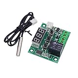
- Arduino SCM & 3D Printer Acc>Module Board
Why this is not automatically a home HVAC thermostat
A thermostat that switches a low-voltage test load demonstrates sensing and threshold logic; it does not establish compatibility with a home’s heating, cooling, fan, or heat-pump controls. Arduino’s 2024 MKR WiFi 1010 project is explicitly heating-only and does not control a blower fan or air conditioner. Other equipment can require different outputs and sequencing, so identify the system’s control interface before designing around it.
For a real mains-connected heater or HVAC installation, the switching device must be rated for the actual voltage, current, and load type. Appropriate isolation, enclosure, overcurrent protection, and compliance with local electrical requirements also matter. A hobby relay board’s stated current rating alone does not show that its circuit layout, terminals, enclosure, or installation are suitable for mains use. The cited project examples do not establish a safe, general-purpose mains wiring recipe.
What’s actually slowing this PC down?
Pick the symptom - the matching free tool is one click away.
Best Value
![Official Arduino Starter Kit [K000007] - 12 DIY Projects with Electronic Components & English Projects Book - Original Kit from Italy](https://m.media-amazon.com/images/I/51fPv6DsjQL._SL160_.jpg)
- Complete DIY Electronics Kit – The Official Arduino Starter Kit includes everything you need to begin exploring the world of electronics and programming, featuring 12 hands-on DIY projects that teach key concepts in coding and circuit design.
- Comprehensive English Projects Book – Comes with an easy-to-follow, detailed project book in English, guiding you through each project step by step, ideal for beginners learning electronics and microcontroller programming.
- Ideal for All Skill Levels – Whether you're a complete beginner or looking to refresh your skills, this kit is perfect for anyone interested in learning electronics, coding, and building creative projects.
- High-Quality, Original Components – Includes a selection of genuine Arduino components sourced from Italy, ensuring durability, reliability, and compatibility with a wide range of Arduino-based projects.
- Perfect for Learning & Teaching – This kit is designed for educational purposes, making it an excellent tool for classrooms, hobbyists, and anyone interested in STEM learning and innovation through hands-on experimentation.
For an illustrative threshold implementation, see ArduinoGetStarted.com’s Arduino heating-system example. For the older Ethernet-equipped Uno design, see the Arduino Project Hub thermostat example; use it as a project reference rather than a current safety or platform standard.
Quick Recap
Product prices and availability are accurate as of the date/time indicated and are subject to change. Any price and availability information displayed on Amazon at the time of purchase will apply.