Do these 3 things before closing this tab:
1Clear out junk files and repair common Windows errors2Fix the driver behind crashes, sound loss and screen glitches3Repair Windows errors before they cause bigger problemsFor most large rail depots, the best answer is a hybrid: use repetitive precast columns, beams, double-tees or wall panels where a factory can produce and erect them quickly, and use cast-in-place concrete for foundations, cores, diaphragms, toppings and irregular interfaces. Choose an all-precast frame when the bay geometry is repetitive, the design can be frozen early, transport routes are dependable and heavy-lift cranes can work safely. Choose predominantly cast-in-place construction when the site cannot receive large elements, the geometry is irregular or late changes are likely.
What the two systems mean on a rail-depot project
Precast concrete
The U.S. General Services Administration defines precast as concrete cast in a reusable form, cured in a controlled environment, transported to the site and lifted into position. Columns, beams, wall panels, double-tees and other members are manufactured away from the depot, then assembled on prepared foundations. Factory production can improve dimensional consistency and allows fabrication to proceed while excavation, foundations and utilities are under way.

As an Amazon Associate I earn from qualifying purchases.
Cast-in-place concrete
Cast-in-place (also called cast-in-situ) concrete is formed, reinforced, placed and cured at the depot. The structure can be shaped around unusual track interfaces, pits, trenches, embedded equipment and one-off geometry. Continuity between pours is naturally developed through reinforcement and construction joints, although the designer must still detail those joints, reinforcement, curing and crack control.
Quick wins for a faster PC:
Repair Windows errors before they cause bigger problemsFix Now →Fix the driver behind crashes, sound loss and screen glitchesFind Drivers →Hybrid construction
A hybrid uses each method where it has the strongest fit. Typical arrangements include precast frame members with cast-in-place footings; precast wall panels around a cast-in-place core; precast beams and planks with a cast-in-place topping that forms a diaphragm; or factory-made members connected by cast-in-place joints and closure pours. This is not a compromise by default: it can separate repetitive production from the depot’s unique foundations, seismic elements and rail-operational interfaces.
#1 Best Overall
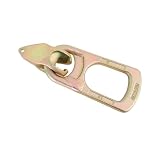
- High-strength steel lifting hoop for precast concrete, with quick release clutch for safe and efficient lifting
- The load limit is 1.5 to 2.5 tons.
- Suitable for various precast concrete lifting applications, such as columns and stairs.
- For the lifting of precast concrete elements, pre-plan and use specialized equipment - improper use may cause damage
- Contact us if you have questions about the product, we will reply you within 24 hours
When precast is the stronger choice
- Repetition: identical or near-identical bays, columns, beams, double-tees and wall panels justify reusable forms and a planned erection sequence.
- Early design freeze: member sizes, connection locations, openings, lifting anchors and embedded items can be released before fabrication.
- Schedule pressure: plant production can overlap with site work, and a total precast frame can be erected from ground level through the roof in one coordinated operation, according to PCI Northeast guidance.
- Rapid enclosure: wall panels and roof members can close the building sooner, protecting interior work from weather and allowing equipment installation to start earlier.
- Reliable access: haul routes, delivery windows, laydown space and crane positions are available without conflicting with live-track operations.
Precast is not automatically cheaper. Its value usually comes from schedule certainty, reduced on-site wet trades and repeatable quality. Those benefits can disappear if every member is unique, transport requires extraordinary permits or the crane must be repeatedly remobilized.
When cast-in-place is the stronger choice
- Constrained delivery: ACI transit guidance says cast-in-place is used when site limitations preclude delivery of large precast elements. Narrow streets, low bridges, weight restrictions, urban restrictions or a depot enclosed by existing tracks can make this decisive.
- Irregular geometry: Sloped roofs, transfer zones, curved walls, deep pits, maintenance trenches and changing bay widths are easier to form on site than to manufacture as one-off precast pieces.
- Late coordination: If crane-runway loads, catenary supports, ventilation openings, fire systems or rail equipment are still changing, cast-in-place work can absorb revisions longer than a factory production slot can.
- Limited lifting capacity: A site without a suitable heavy crane, stable crane pads or safe lifting windows may not support economical precast erection.
- Monolithic behavior: Where continuity, stiffness and load transfer are difficult to achieve with practical joints, a cast-in-place frame or diaphragm can simplify the structural concept.
The trade-off is a longer sequence of formwork, reinforcement, placement, vibration, curing, stripping and inspection at the depot. Weather, concrete-delivery interruptions and congestion around tracks must be managed directly.
Schedule and enclosure: what actually gets faster
Precast can shorten the critical path because fabrication proceeds away from the site while foundations and underground services are built. Once foundations reach the required strength and survey tolerances, erection can proceed bay by bay. Fewer field pours also reduce waiting for curing before subsequent trades can load or enclose the structure.
The Tool Desk
Outbyte Driver Updater FREEScan for outdated or missing drivers - takes under a minuteDriver Scan →Outbyte PC Repair FREERepair Windows errors before they cause bigger problemsFix Now →That advantage depends on decisions made early. Shop drawings, connection design, lifting inserts, fire requirements, openings and finishes must be coordinated before molds are committed. A late change can require a new mold, a production-slot change or an expensive field modification. Design-assist by the precaster, structural engineer and general contractor is useful for scheduling, logistics, code compliance, durability and cost planning.
Cast-in-place work has more serial activities: erect forms, place reinforcement and embeds, pour, cure, strip and move the forms. Reusable table forms and pumps can make repetitive bays efficient, but the operation remains exposed to rain, temperature, concrete-supply continuity and access for placing equipment. A detailed pour-cycle plan is as important as a precast erection schedule.
Geometry, standardization and late changes
Standardization is the economic engine of precast. Establish a bay module and repeat it wherever rail clearances, service roads, crane runways and maintenance equipment permit. Standardize member depths, connection families, panel widths, lifting points and openings. The Hong Kong code recommends standardizing precast elements where possible; the same principle helps a North American depot reduce molds, design effort and erection variation.
Rank #2

- Working load limit 1.5T - 2.5T
- Use in a range of lifting applications with pre cast concrete products and elements such as columns and staircases
- This product has been designed to ensure that the lifting of precast concrete for example for columns, or staircases is done as safely and efficiently as possible.
- When lifting prefabricated concrete products pre-planning and the use of specialist equipment is essential. Not using the correct equipment could result in serious damage to the product and surrounding area, not to mention a huge danger to the life of anybody working in the area.
- 【Widely Application】 The eyebolts heavy duty is a fixing and linking tool used in ports, electric power, shipbuilding, petrochemical, mining, railway, automobile manufacturing, large-size transportation, marine rescue, airport construction, bridges and other important industries as well as mechanical equipment for infrastructure projects.
Do not force standard members into areas that are inherently unique. Track pits, wheel-lathe rooms, inspection platforms, transfer girders, blast walls, stair and elevator cores, drainage sumps and interfaces with existing structures often belong in cast-in-place or hybrid packages. A one-off precast piece may cost more than a well-planned site pour once mold fabrication, transport and special lifting are included.
At the concept stage, create a change-control date for each package. Changes before that date can be incorporated into the member design; changes afterward should be evaluated for redesign, field-cast closure, supplemental steel or a deliberate shift to cast-in-place.
Logistics: the feasibility test before selecting precast
Precast transfers work from the site to a supply chain. Complete a route and erection study before committing to member sizes.
- Map the route. Check plant distance, bridge capacities, turning radii, overhead lines, restricted streets, permit requirements and delivery times. A route that works for a short wall panel may fail for a long beam or double-tee.
- Confirm weights and dimensions. Record shipping weight, overall length, center of gravity, lifting points and required trailer type for every member family.
- Reserve crane capacity. Check radius-specific capacity, boom configuration, ground-bearing pressure, wind limits, pick-and-carry restrictions and whether a second crane is needed for tailing or panel rotation.
- Design the work zone. Provide crane pads, delivery lanes, laydown areas, exclusion zones and temporary bracing locations. Keep emergency access and rail-operational clearances open.
- Sequence the erection. Define the first stable bay, brace each member until the permanent system is complete, and coordinate roof, wall, diaphragm and connection inspections before releasing the crane.
- Set delivery windows. Align trucks and lifts with possessions, outages and limits on work near live tracks. A theoretically fast erection can lose its advantage if only short nighttime windows are available.
Cast-in-place logistics are different rather than absent. Verify concrete-plant capacity, haul time, pump reach, washout arrangements, reinforcement and formwork storage, backup supply, lighting and weather protection. For a depot surrounded by active rail operations, the smaller truck movements of a cast-in-place scheme may be safer than occasional oversized loads—or they may create more frequent conflicts; the site-specific traffic plan decides.
Connections, continuity and seismic design
The Building and Construction Authority handbook identifies the main structural difference between cast-in-situ and precast buildings as structural continuity. Cast-in-place continuity is inherent in the continuous reinforcement and concrete placement. Precast continuity must be deliberately created through component connections.
For every precast connection, the design team must establish:
Rank #3

- Premium Heavy-Duty ABS Material for Long-Lasting Performance: This precast balcony Forms is crafted from high-grade industrial ABS plastic, a rigid and impact-resistant material that stands up to repeated concrete pouring, demolding, and outdoor job site wear. Unlike flimsy single-use forms, it resists cracking, warping, and fading, ensuring consistent shape and structural integrity for every precast balcony component you produce.
- Extremely Reusable Design for Maximum Cost Savings: Engineered for repeated use dozens of times without losing shape or functionality, this form eliminates the need to constantly replace disposable forms for precast balcony projects. It drastically cuts material replacement costs, reduces waste on construction sites, and delivers a high return on investment for small construction teams, precast factories, and DIY building enthusiasts alike.
- User-Friendly & Easy to Operate for All Skill Levels: Designed with intuitive construction and smooth inner walls, this balcony mould requires no complex tools or professional expertise to use. The straightforward assembly and demolding process speeds up precast production workflow, minimizes labor time, and prevents concrete sticking for clean, smooth finished balcony pieces every time
- Standard 88cm Height for Universal Precast Balcony Compatibility: Made to a precise 88-centimeter height, this mold fits standard precast balcony construction specifications, making it ideal for residential building projects, commercial construction, balcony renovation, and custom precast concrete component manufacturing. It creates uniform, professional-grade balcony parts that meet industry size standards.
- Versatile Industrial-Grade Building Form for Construction Projects: Perfect for on-site precast work and factory-based mass production of concrete balcony components, this form delivers consistent, high-quality results with every use. Its durable ABS construction and reusable design make it a reliable, long-term tool for contractors, builders, and precast concrete specialists looking to streamline production and lower operational costs.
- strength and load paths for gravity, wind, braking, thermal and accidental actions;
- ductility and deformation capacity, especially in seismic zones;
- tolerance for erection and accumulated dimensional variation;
- resistance to volume change, shrinkage and thermal movement;
- durability against water, deicing salts, pollutants and freeze-thaw exposure;
- fire resistance and protection of reinforcement or connectors;
- inspection, grouting, welding or bolting procedures and acceptance criteria.
NIST and NEHRP publish separate guidance for precast and cast-in-place diaphragms. A precast floor or roof may need a cast-in-place topping slab to distribute lateral forces, tie members together and provide the required diaphragm strength and stiffness. The topping is not merely a finish: its reinforcement, interfaces, curing and construction sequence are part of the seismic load path.
For a seismic depot, analyze the structure through erection stages as well as in its final state. A member may be stable after the diaphragm and permanent connections are complete but vulnerable during a partially erected sequence. Detail collector elements, chord reinforcement, joints, wall-panel anchors and foundation ties as one system. Provide seismic separations where building masses, heights or stiffnesses differ, and coordinate those joints with tracks, roof drainage, fire stopping and cladding.
Train vibration, movement and operational interfaces
ACI transit guidance calls out vibration, drainage, joints and emergency access for transit structures. A depot must be checked for vibration from moving and idling trains, wheel impacts, maintenance machinery, bridge cranes and equipment mounted to the structure. Serviceability criteria—acceleration, frequency, deflection and crack control—may govern member depth or connection stiffness even when ultimate strength is adequate.
Recommended Free Tools
Keep vibration-sensitive rooms, offices and precision maintenance equipment out of poorly isolated zones where practical. Coordinate rail clearances, overhead systems, inspection pits, drainage channels, fire lanes and removable equipment paths with column and wall locations before the structural grid is frozen. Detail joints so they do not create a trip hazard, leak path or obstruction to bogie movement.
Drainage deserves an explicit interface plan. Roof and wall joints, floor falls, trench drains, sumps and wash-down systems must accommodate construction tolerances and movement. A precast panel joint that is structurally sound can still fail operationally if water reaches reinforcement, electrical equipment or a track pit.
Fire resistance and durability
Both systems can satisfy fire and durability requirements when they are designed and maintained correctly. Factory production does not remove the need to verify concrete cover, reinforcement placement, connector protection, joint fire stopping, crack widths and water ingress.
Specify the required fire rating for columns, beams, walls, floors, roof members and separation joints. Check how connection hardware behaves under fire exposure and how a topping or grout key contributes to the rated assembly. For cast-in-place work, control curing, placement temperature, consolidation and construction-joint preparation; defects in any of these can reduce durability.
Free tools Windows power users keep installed
One-click scans. No signup required.
For precast, inspect lifting anchors, bearing pads, welds, bolts, grouted sleeves, sealants and closure pours. Plan replacement access for seals and joints exposed to wash-down water, salts or freeze-thaw cycles. Lifecycle maintenance should be part of the initial comparison, not an afterthought.
Safety and temporary stability
OSHA Subpart Q contains separate requirements for cast-in-place concrete (1926.703) and precast concrete (1926.704). Apply the edition and local rules governing the project, and assign responsibility for the engineered means and methods.
Precast hazards include suspended loads, trailer movement, crane overturning, pinch points, dropped objects, wind on panels and progressive instability. The erection plan should show exclusion zones, tag-line use, communications, brace installation, release criteria and rescue access. Never remove temporary bracing because a member “looks stable”; remove it only after the permanent load path is complete and inspected.
Cast-in-place hazards include formwork collapse, rebar impalement, pump-line movement, concrete pressure, working at height, stripping operations and incomplete shores. Inspect forms, reshoring, access platforms and embeds before each pour. Coordinate concrete trucks and pumps with rail protection, spotters and emergency routes.
Cost: compare the whole installed and lifecycle system
No transferable rail-depot cost, schedule or defect-rate statistic establishes that one system is universally cheaper. A credible estimate must compare the complete installed solution rather than the concrete unit price.
Best Value

- OPTIMUM DESIGN - designed for deep, precise cuts in hard materials such as hard/reinforced concrete, precast panels and hard stone such as river rock, granite, quartz and marble
- PREMIUM DURABILITY - constructed with solid steel for added stability along with diamond encrusted 8mm segments for accurate, deep cuts
- SEGMENT WIDTH - 0.163" width
- RING WHEEL - includes 1 ring wheel with blade
- USE WET ONLY - designed for Husqvarna K970, K3600, K6500
| Cost and risk item | Precast emphasis | Cast-in-place emphasis |
|---|---|---|
| Design and preconstruction | Design-assist, connection engineering, shop drawings, molds and early release | Formwork design, pour-cycle planning, reshoring and field coordination |
| Site logistics | Transport permits, haulage, crane, crane pads, laydown and temporary bracing | Concrete supply, pumps, formwork storage, reinforcement handling and weather protection |
| Schedule value | Off-site fabrication overlaps foundations; rapid enclosure can release interior work | More sequential forming, placing, curing and stripping activities |
| Quality and inspection | Factory production plus field connection, grout, sealant and tolerance inspections | Continuous field inspection of forms, reinforcement, placement, curing and joints |
| Lifecycle exposure | Panel and structural joints, bearings, sealants, connectors and water ingress | Cracking, construction joints, curing-related defects and repairs to cast surfaces |
Put a value on the opening date, possession windows, weather exposure and the cost of maintaining temporary facilities. Include redesign risk if the design changes after precast fabrication begins. Include joint inspection and repair allowances for both systems. The least expensive bid is not necessarily the least expensive depot if it delays commissioning or creates difficult access for future repairs.
A decision workflow for the project team
- Freeze the governing inputs. Record jurisdiction and code edition, seismic design category, footprint, bay module, clear heights, crane-runway loads, soil and foundation concept, track interfaces, fire strategy and target opening date.
- Map logistics. Confirm plant radius, route restrictions, element weights, crane positions, laydown, temporary bracing and erection windows around rail operations.
- Measure repetition. Standardize bay widths, double-tees, beams, columns and panels where practical; assign one-off geometry and sensitive interfaces to cast-in-place packages.
- Model structural and service behavior. Design connections and diaphragms, including any cast-in-place topping; check vibration, thermal movement, drainage, crack control, seismic joints and staged stability.
- Price the whole life. Include design-assist, molds, transport, cranes, site labor, curing and weather risk, inspection, maintenance, joint repairs and schedule consequences.
- Hold a constructability review. The structural engineer, precaster, general contractor, rail operator and safety team should approve the selected system and the erection or pour sequence before release.
Practical hybrid patterns for depots
Precast frame with cast-in-place foundations
Use standardized columns and beams above footings while casting foundations, pile caps, pits and grade beams to suit variable soil and track geometry. Survey tolerances and anchor-bolt placement become critical before erection.
Precast walls with a cast-in-place core
Wall panels can enclose repetitive bays while a cast-in-place stair, elevator or service core supplies stiffness, fire separation and a robust vertical load path. Coordinate panel anchors with core movement and seismic joints.
Precast floor or roof members with a structural topping
Double-tees or planks provide rapid coverage; a reinforced cast-in-place topping completes the diaphragm, ties members together and can provide the required surface falls or equipment support. Design the interface for shear transfer, shrinkage and construction loading.
Cast-in-place special zones inside a precast shell
Keep transfer girders, heavy crane-support zones, pits, wash-down areas and irregular equipment foundations cast in place while using precast for the regular envelope and roof. Isolate the special zones with deliberately detailed joints rather than improvised field cuts.
Common failure modes and how to prevent them
- Choosing precast before the route is proven: perform the route, permit and crane study before fixing member dimensions.
- Freezing the grid too late: establish release dates for openings, embeds, rail equipment and fire systems; after fabrication, evaluate every change for cost and structural effect.
- Treating connections as details to be solved later: design strength, ductility, tolerances, durability and inspection together with the members.
- Ignoring erection-stage stability: specify the first stable bay, temporary bracing and release inspections in the erection documents.
- Assuming a topping automatically creates a diaphragm: design its reinforcement, collectors, chords, joints, curing and connection to the precast members.
- Comparing only concrete quantities: include cranes, molds, transport, formwork, weather, possessions, maintenance and schedule value.
- Underestimating rail operations: coordinate vibration, clearances, drainage, emergency access and work near live tracks with the operator before construction.
Bottom-line selection
Select precast when repetition, early certainty, transport access and lifting capacity are real project advantages. Select cast-in-place when geometry, access or changing requirements dominate. For a large train maintenance or stabling building, a hybrid scheme usually gives the most resilient balance: industrialize the repeatable structure, and cast the foundations, diaphragms, cores and irregular rail interfaces that need continuity or adaptability.
Quick Recap
Product prices and availability are accurate as of the date/time indicated and are subject to change. Any price and availability information displayed on Amazon at the time of purchase will apply.

