Do these 3 things before closing this tab:
1Clear out junk files and repair common Windows errors2Scan for outdated or missing drivers - takes under a minute3Repair Windows errors before they cause bigger problemsRecapping—replacing an old radio’s electrolytic and paper capacitors—is a sensible first restoration step, but it is not a matter of replacing every capacitor you can see. Unserviced tube radios can contain several hundred volts, retain a charge after being unplugged, and may have a chassis connected to the mains. Identify the exact circuit first, replace the parts most likely to fail, use the correct voltage and safety ratings, and power the set up through current limiting.
This guide applies broadly to vintage tube and early solid-state radios, but the schematic and service data for the particular model always control the final decision.
As an Amazon Associate I earn from qualifying purchases.
What recapping does
Recapping normally means replacing aged paper capacitors, electrolytic capacitors, and any unsuitable capacitors connected to the AC mains. Paper insulation commonly absorbs moisture and develops leakage; electrolytics can dry out or lose their oxide dielectric. A radio that still plays is therefore not necessarily reliable or safe. See the Antique Radio recap guide for the underlying failure modes and workflow.
A leaky coupling capacitor can put excessive current through an output tube’s control grid circuit, causing distortion, overheating, tube damage, or output-transformer damage. Failed filter electrolytics can produce loud hum, ripple, overheating, and stress on the rectifier or power transformer. A capacitor that fails short can damage other components or create a shock or fire hazard.
#1 Best Overall

- ALLECIN Electrolytic Capacitors Kit contain 24 Different Values In-line Aluminum Capacitors - Perfectly suitable for variety electronic experiments.
- Features & Advantages : Large capacity and small size. Ripple current resistance - small loss tangent, small leakage current, low internal resistance and low ripple.
- Dielectric material: aluminum electrolytic. Lead description: long lead = positive "+"; short lead = negative "-".
- Wide Application : In-line electrolytic capacitors are widely used in household appliances and various electronic products, and are also very suitable for DIY circuit boards.
- Humanized packaging for easy storage and use. # Please confirm the capacitance, voltage and volume before purchasing.
Recapping does not guarantee that the radio will work. Tubes, resistors, switches, coils, transformers, speakers, dial mechanisms, and alignment may still require attention.
Safety comes first
Do not casually plug in an unknown vintage radio. Unplug it before removing the chassis. Tube equipment may contain several hundred volts DC, and filter capacitors can remain charged after the cord is removed.
- Use a properly rated digital multimeter, insulated probes, eye protection, and insulated clip leads.
- Discharge capacitors with a suitable resistor-and-lead discharge tool. Do not routinely short a charged capacitor with a screwdriver.
- Use one-hand measurement technique where appropriate and keep the other hand away from the chassis.
- An AC/DC transformerless radio may have a chassis connected directly or indirectly to one side of the mains. Never assume the chassis is safe, isolated, or grounded.
- An isolation transformer can reduce a particular shock path when working on a transformerless chassis; a Variac alone does not provide galvanic isolation.
- Never work on an energized chassis while tired, distracted, or uncertain about the circuit.
If you cannot read the schematic, identify the mains and high-voltage sections, or safely verify a discharged chassis, stop and use a qualified technician or an experienced radio club. The St. Louis antique-radio inspection guide provides additional safety and inspection guidance.
1. Identify the radio before ordering parts
- Photograph the cabinet, chassis top and underside, tube layout, wiring, and every capacitor marking.
- Record the manufacturer, model number, chassis number, and any service or production numbers.
- Obtain the schematic, parts list, and service information.
- Compare the actual wiring with the schematic. Previous repairs may contain wrong values or altered connections.
- Mark every candidate capacitor on a printed schematic or spreadsheet.
For each part, record its reference number, capacitance, voltage rating, polarity, physical location, and connection points. Also note whether it is connected to B+, the chassis, the AC line, an audio stage, or a tuned RF/IF circuit. A faded marking on an installed part is not more authoritative than the service data. The capacitor-marking guide from JustRadios is useful when old notation is difficult to interpret.
2. Which capacitors usually need replacement?
Waxed and molded paper capacitors
Wax-coated cardboard tubes, axial paper parts, and many molded-paper capacitors are common replacement candidates in old tube radios. Some black-bodied “Black Beauty” parts, Micamold-style paper parts, and capacitor blocks are also paper types despite their appearance. Do not mistake a plastic-looking body for a modern reliable film capacitor.
Rank #2

- 24 Values, 480pcs Total: Includes 20pcs of each value (10pF, 22pF, 30pF, 47pF, 100pF, 220pF, 330pF, 470pF, 1nF, 2.2nF, 3.3nF, 4.7nF, 6.8nF, 10nF, 22nF, 47nF, 68nF, 100nF, 220nF, 470nF, 1uF, 2.2uF, 4.7uF, 10uF), covering a wide range for diverse electronics projects.
- Premium Quality & Durability: Multilayer monolithic ceramic capacitors with 50V withstand voltage, ±10% tolerance, and epoxy resin coating for humidity resistance and long-term reliability.
- Organized Storage Box: Compact re-sealable plastic case with labeled compartments to prevent mixing and ensure easy access. Ideal for hobbyists and engineers.
- Versatile Applications: Perfect for bypass circuits, filtering, signal coupling, DIY electronics, industrial control systems, and electron experiments.
- Clear Markings & Easy Identification: Each capacitor features printed capacitance codes (e.g., 104=100nF=0.1uF), simplifying component selection during assembly.
Electrolytic capacitors
These include large aluminum cans on the chassis, cardboard-covered tubular parts, and axial electrolytics. They are polarized and are especially important in the power-supply filter. A replacement’s positive and negative connections must match the circuit—not merely the physical orientation of the original part.
AC-line capacitors
Old line-bypass capacitors may no longer meet modern safety requirements. A capacitor connected across line and neutral is an across-the-line position and normally requires an appropriately rated Class X safety capacitor. A capacitor connected from line or neutral to chassis or earth is a line-to-ground position and normally requires a suitably rated Class Y safety capacitor. An ordinary 630 VDC film capacitor is not automatically an acceptable mains replacement. See the safety-capacitor information from JustRadios and the Vishay safety-capacitor information.
Parts usually left alone
Mica, ceramic, polystyrene, and clearly modern film capacitors are generally left in place unless testing or symptoms indicate failure. Mica and ceramic parts are common in tuned RF and IF circuits, where changing the value or dielectric can alter frequency, stability, or alignment. They are not immune to failure, but automatic replacement is poor practice. The RadioMuseum discussion of capacitor types explains these exceptions.
3. Read old capacitor markings
MFD,MF, andμFmean microfarads.MMFD,μμF, andpFindicate much smaller values.0.01 μFequals10 nF.0.047 μFequals47 nF.- An old
.05 MFDpaper capacitor may correspond to the modern standard value0.047 μFin an ordinary coupling or bypass position, subject to the schematic and circuit function.
A band, dot, or “foil” marking on an old paper capacitor may identify the outer-foil lead. It is not a positive-polarity marking. Electrolytic symbols identify polarity; on multi-section cans, triangles, squares, half-moons, or other symbols identify individual sections.
4. Choose the replacements
Capacitance
Use the schematic value where possible. A nearby modern standard value can be acceptable in some coupling and bypass positions, but use greater care in oscillator, IF, RF, tone-control, feedback, precision, and power-supply circuits. Do not apply a universal percentage rule.
Rank #3
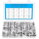
- Comprehensive Kit of 200PCS Includes 15 commonly used capacitor values from 0.1uF to 1000uF, with voltage ratings of 10V, 16V, 25V, and 50V. Each value is neatly organized in a labeled plastic storage box for easy access and use.
- Clear Polarity Markings Aluminum electrolytic capacitors with radial leads. Long lead = positive (+), short lead = negative (−), making installation easier and safer.
- Durable and Stable Designed with an operating temperature range of -40℃ to +105℃ and ±20% tolerance, ensuring stable and reliable performance under harsh conditions.
- Low ESR & Ripple Resistance Features low equivalent series resistance (ESR) and high ripple current resistance, ideal for smoothing, filtering, and timing circuits in power supply and audio applications.
- Wide Applications Perfect for hobbyists, engineers, and technicians working on TVs, monitors, speakers, game consoles, amplifiers, and other consumer electronics
For electrolytics, use the same nominal capacitance where practical. A modestly higher value may be acceptable in some filter positions, but increasing capacitance can increase rectifier surge current and exceed the circuit’s design limits. Do not casually change a rectifier input capacitor.
Free tools Windows power users keep installed
One-click scans. No signup required.
Voltage rating
Use a replacement rated at least as high as the original and adequate for the circuit’s actual maximum voltage, including startup surge. A 630 VDC film capacitor is a common choice for many paper-capacitor positions, but it is not suitable for every position. Electrolytics in tube-radio supplies may require 350, 400, 450, or 500 V ratings depending on the service data and measured B+ voltage.
A higher rating is not automatically better: the part may be larger, harder to mount, and more expensive. Never use a part below the required rating.
Construction and polarity
- Metallized polyester or polypropylene film capacitors suit many paper-capacitor replacements.
- Axial parts often fit point-to-point vintage wiring; radial parts are also suitable when safely mounted on a terminal strip or tie point.
- Use non-polarized film capacitors for ordinary non-electrolytic positions.
- Use bipolar electrolytics only where the original circuit requires a non-polarized electrolytic.
- Do not substitute silver mica, ceramic, or polystyrene parts interchangeably in tuned circuits.
5. Tools and materials
- Temperature-controlled soldering iron
- Solder sucker and solder wick
- Small diagonal cutters and long-nose pliers
- Digital multimeter rated for the expected voltage
- Insulated clip leads and temporary labels
- Resistor-based capacitor-discharge tool
- Heat-shrink tubing or insulating sleeving
- Schematic and service manual
- Camera or phone
- Dim-bulb tester or another current-limited first-power arrangement
- Isolation transformer where the circuit and test setup require it
For one radio, a model-specific parts list is usually more economical than a large bulk kit. Specialist suppliers offer 630 V axial and dipped-film kits, AC/DC electrolytic kits, higher-voltage electrolytic kits, and X/Y safety kits. Distributors such as DigiKey and Mouser are useful when you need a documented manufacturer part. Stock, shipping, and prices change, so verify current listings before purchase.
6. Replace one capacitor at a time
- Unplug the radio. Remove tubes only if the service procedure calls for it, and label their positions.
- Discharge the high-voltage capacitors with the appropriate resistor-based tool.
- Photograph the work area before disturbing any wiring.
- Choose one capacitor from the schematic and locate both of its actual connection points.
- Confirm the replacement has the correct capacitance, voltage, polarity, safety class, and physical clearance.
- Remove the old part, preferably one lead at a time. Do not rely on proximity to identify a terminal.
- Install the new part along the original route. Mechanically secure it before soldering.
- Protect the leads with sleeving where they could touch metal, another terminal, a coil, or a moving mechanism.
- Inspect the joint, trim excess lead, and ensure no adjacent terminals were bridged.
- Mark the schematic or log before moving to the next capacitor.
Keep high-voltage leads short and insulated, but preserve the original lead dress. In RF and IF sections, excess length or a moved wire can cause oscillation or loss of sensitivity. Avoid overheating tube-socket lugs, switch contacts, coil wires, and fragile terminal strips.
The Tool Desk
Outbyte PC Repair FREERepair Windows errors before they cause bigger problemsFix Now →Outbyte Driver Updater FREEScan for outdated or missing drivers - takes under a minuteDriver Scan →Rank #4

- 10pf - 10uf 30 value 300 pcs capacitor set, 30 individual compartment
- Each compartment has a plastic cover/door that opens and closes with a nice positive snap.
- 🟡 10pf 15pf 22pf 33pf 47pf 68pf 100pf 220pf 470pf 680pf
- 🔵 1nf 2.5nf 2.2nf 3.3nf 4.7nf 6.8nf 10nf 22nf 47nf 68nf
- 🔴 0.1uf 0.15uf 0.22uf 0.33uf 0.47uf 0.68uf 1uf 2.2uf 4.7uf 10uf
7. Replacing a multi-section electrolytic can
A can may contain two, three, or more filter sections. Each section has its own positive terminal, identified by a symbol or marking, and may share a negative connection. The metal can is often common negative, but it may be insulated from the chassis or connected differently. Never assume.
- Copy every can symbol, capacitance, voltage, positive terminal, and negative connection onto your log.
- Trace each terminal to the schematic and chassis; do not identify sections by physical position alone.
- Install individual electrolytics beneath the chassis, observing each section’s polarity and rating.
- Insulate and secure the new parts so their leads cannot contact the can, chassis, or neighboring terminals.
- Either remove the original can electrically or leave it mounted only after all of its electrical terminals are safely isolated.
Restuffing the original can preserves appearance but adds mechanical and heat-related work. It does not make the original internals trustworthy; they must be disconnected or replaced inside the can.
8. Replacing capacitors in AC/DC radios
Transformerless radios often derive tube-heater power directly from the mains. Depending on the design and plug orientation, the chassis may be connected to one side of the line. The cord, switch, insulation, line capacitors, and any isolation components are part of the safety system.
Map every mains connection before soldering. Replace an across-the-line part with the correct X-rated safety capacitor and a line-to-chassis or line-to-earth part with the correct Y-rated type. A high DC voltage printed on an ordinary film capacitor does not replace the required safety certification. If you are unfamiliar with hot-chassis equipment, use an isolation transformer and obtain experienced help.
Quick wins for a faster PC:
Fix the driver behind crashes, sound loss and screen glitchesFind Drivers →Repair Windows errors before they cause bigger problemsFix Now →Scan for outdated or missing drivers - takes under a minuteDriver Scan →9. Controlled first power-up
- Compare the completed chassis with the schematic and your replacement log.
- Recheck every electrolytic polarity and inspect for accidental shorts.
- Inspect the power cord, fuse, switch, transformer, rectifier, and line capacitors.
- Power the radio through a dim-bulb tester or another suitable current-limited method.
- Watch for a bright lamp, smoke, odor, excessive heat, abnormal tube glow, or rising current.
- Measure key DC voltages against the service data when it is safe to do so.
- Power down and discharge the capacitors before touching the chassis again.
Do not treat “plug it in and see” as a test procedure. If the tester lamp glows brightly, a fuse blows, or the transformer becomes hot, stop immediately and investigate.
Best Value
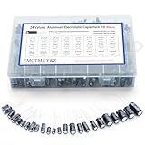
- 24 Values & 500pcs Comprehensive Kit: Covering 0.1uF to 1000uF with voltage ratings from 10V to 50V, this kit includes 24 essential capacitance values and 500 pieces total. Perfect for prototyping, repairs, and diverse electronic projects.
- Optimized Quantity for Practical Use: Each value is carefully curated with higher quantities for commonly used capacitors (e.g., 30pcs of 0.1uF, 2.2uF, 3.3uF) and balanced stock for specialized values (e.g., 10pcs of 680uF, 1000uF), ensuring you always have what you need.
- Premium Quality & Durability: Made with high-purity aluminum and rated for -40℃ to +105℃ operation. Features low leakage current (±20% tolerance) and long lifespan, ideal for power supplies, amplifiers, and industrial applications.
- User-Friendly Transparent Storage Box: All capacitors are organized in a sturdy, labeled compartment box. Clear lids and anti-slip design make storage effortless and components easily accessible.
- Versatile for Professionals & Hobbyists: Repair TVs, motherboards, game consoles, or build DIY circuits. Perfect for engineers and electronics enthusiasts seeking a reliable, all-in-one capacitor solution.
10. Troubleshooting after recapping
| Symptom | Likely checks | Action |
|---|---|---|
| Loud hum unaffected by the volume control | Filter electrolytic polarity or value, missing ground, open power-supply resistor, incorrect can wiring | Power down, discharge, and compare every connection with the schematic. |
| No audio or weak audio | Coupling capacitor, output-tube grid voltage, socket wiring, volume control, speaker, output transformer, drifted resistors | Measure against service data rather than replacing random parts. |
| Oscillation, instability, or poor sensitivity | Miswired capacitor, excessive lead length, disturbed coil or trimmer wiring, wrong RF/IF capacitor type | Restore original lead dress and check whether alignment is required. |
| Bright dim-bulb lamp, blown fuse, or hot transformer | Reversed electrolytic, shorted replacement, incorrect line wiring, failed rectifier or tube, existing transformer fault | Stop immediately; do not keep applying power. |
A capacitance meter can show a nominal value while missing unacceptable leakage at operating voltage. For old paper and electrolytic parts, replacement is often more practical than relying on a basic capacitance reading. For mica, ceramic, and modern film parts—especially tuned components—targeted testing is more appropriate.
11. Alignment and the limits of recapping
Correctly replacing an ordinary coupling or bypass capacitor should not normally require RF alignment. Replacing a capacitor in an oscillator, RF, IF, or other tuned circuit can change frequency or tracking and may require alignment using the service procedure and suitable test equipment. Do not substitute dielectric types casually in these positions.
Recapping will not automatically repair bad tubes, drifted or open resistors, dirty controls or band switches, broken dial cords, open coils, defective IF transformers, speaker damage, transformer faults, cabinet damage, or misalignment. Treat it as one stage of restoration, not a guarantee of safe performance or a complete repair.
Crashes, No Sound, or Screen Glitches?
Random freezes, missing sound and display glitches usually trace back to one bad driver. Find and replace yours safely.Free scan · under a minutePC Slower Than It Used to Be?
A free scan shows the junk files, broken settings and background clutter dragging Windows down - then fixes them in one click.Free scan · Windows 10 & 11Copyable capacitor inventory
Radio make/model: __________________________  Chassis: __________________

Ref. | Original value | Voltage | Polarity | Connection/function | New part | Done
-----|----------------|---------|----------|---------------------|----------|-----
C___ | ______________ | _______ | ________ | ___________________ | ________ | [ ]
C___ | ______________ | _______ | ________ | ___________________ | ________ | [ ]
C___ | ______________ | _______ | ________ | ___________________ | ________ | [ ]
C___ | ______________ | _______ | ________ | ___________________ | ________ | [ ]

Before power-up: [ ] polarity checked  [ ] line parts verified  [ ] shorts checked
[ ] cord/switch inspected  [ ] current limiter ready  [ ] schematic comparison complete
When to stop
Stop when the schematic does not match the chassis, a mains connection is unclear, an electrolytic’s polarity cannot be established, the chassis is damaged, or a fault persists after the documented replacements. High-voltage and hot-chassis work rewards careful diagnosis, not speed. A qualified technician can prevent a dangerous mistake and may save an irreplaceable transformer, speaker, or tube.
Quick Recap
Product prices and availability are accurate as of the date/time indicated and are subject to change. Any price and availability information displayed on Amazon at the time of purchase will apply.

