You can build a beginner-friendly laser tripwire alarm with an Arduino, an LDR/photoresistor, a buzzer, an LED, and a reset button. The laser shines continuously at the LDR; when the beam is interrupted, the sensor reading changes and the Arduino latches the alarm until you press reset.
This is an educational tabletop or room-entry demonstrator—not a certified security system. Never aim a laser at eyes, vehicles, aircraft, roads, mirrors, or other reflective surfaces. Keep the beam below eye level or above head height and use the lowest-power documented module that works.
As an Amazon Associate I earn from qualifying purchases.
How the Arduino laser alarm works
The laser does not detect motion directly. It detects whether a specific line-of-sight beam is reaching the sensor.
Laser beam → LDR voltage divider → Arduino A0
                                      ↓
Buzzer + status LED- Beam present: concentrated light reaches the LDR.
- Beam interrupted: the LDR’s analog voltage changes when an object blocks the beam.
- Alarm triggered: the Arduino decides that the change exceeds the calibrated threshold.
- Alarm latched: the buzzer and LED remain active until the reset button is pressed.
An Arduino Uno’s analog input provides a reading from 0 to 1023 for this project. The LDR is not a digital on/off switch; software converts its analog reading into a decision. The Arduino Uno Rev3 specifications list 5 V operation, six analog inputs, 14 digital I/O pins, and a 20 mA maximum per I/O pin.
#1 Best Overall

- The sensor uses a non-modulated laser receiver.
- Please use this sensor in dark environments or indoors where no light. Sunlight or other fixtures may interfere.
- It output high level when receive laser signal, and low level when not.
- If you buy 1, you will receive 5pcs sensor
- If you have any issue when using our product,or you need product use documentation, please contact us directly for assistance.we will solve your problem in 24 hours.
Parts and tools
| Quantity | Part | Notes |
|---|---|---|
| 1 | Arduino Uno Rev3 or compatible 5 V board | A Nano can be used later for a smaller enclosure. |
| 1 | Documented visible laser module | Use a module with an integrated driver, not an unknown bare diode. |
| 1 | LDR/photoresistor | Readily available in beginner electronics kits. |
| 1 | 10 kΩ resistor | A starting value; another value may work better with your LDR. |
| 1 | Passive piezo buzzer | Works with Arduino tone(). |
| 1 | LED | Status indicator. |
| 1 | 220–330 Ω resistor | Limits LED current. |
| 1 | Pushbutton | Used to reset the latched alarm. |
| 1 | Breadboard, jumper wires, USB cable and computer | Use rigid mounts for the laser and sensor. |
For example, Adafruit’s documented 5 mW, 650 nm laser module is specified for 2.8–5.2 V DC, up to 25 mA, and includes an integrated driver. Its product page lists it as Class IIIa; do not describe a 5 mW laser as harmless or eye-safe.
Wire the circuit
LDR voltage divider
Arduino 5V ---- LDR ----+---- A0
                        |
                       10kΩ
                        |
Arduino GND -----------
Connect one LDR leg to 5 V and the other to A0. Connect the 10 kΩ resistor between A0 and GND. Depending on the LDR and resistor arrangement, illumination may make the analog value rise or fall. Do not assume the comparison direction—measure it.
Rank #2
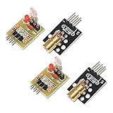
- Operating voltage: 5V
- Source wavelength: 650 nm
- Apply to: for Arduino AVR
- Model: 1*Laser Receiver Sensor Module+ 1* KY-008 Laser Transmitter Module
- Laser Receiver Sensor Module uses the non modulated laser receiver, please use in the room where without the light, the sunlight or other lamps and lanterns will interfere, suggested in the dark environment use.
Pin connections
| Component | Connection |
|---|---|
| LDR leg 1 | Arduino 5V |
| LDR leg 2 | Arduino A0 |
| 10 kΩ resistor leg 1 | Arduino A0 |
| 10 kΩ resistor leg 2 | Arduino GND |
| Passive buzzer positive | Arduino D9 |
| Passive buzzer negative | Arduino GND |
| LED anode | Arduino D7 through a 220–330 Ω resistor |
| LED cathode | Arduino GND |
| Pushbutton leg 1 | Arduino D2 |
| Pushbutton leg 2 | Arduino GND |
| Laser positive | Arduino 5V or a suitable regulated supply |
| Laser negative | Arduino GND |
The button uses INPUT_PULLUP, so no external pull-up resistor is needed. It reads LOW when pressed.
Recommended Free Tools
Do not connect a bare laser diode directly to an Arduino output pin. Bare diodes normally require current regulation. Verify the module’s voltage and current requirements. For a software-controlled laser supply, use a transistor or MOSFET driver rather than powering the laser from an I/O pin.
Rank #3

- 【Laser Sensor Module】Size: 1.52CM * 2.22CM; Power supply voltage: 5V;Output:When the laser output it's High level; when no laser light output it's low level;
- 【Laser Sensor Module】This sensor uses a non-modulated laser receiver, please use on the room which is dark.the sun or other lighting will interfere the using of the product.suggest use in a dark environment.
- 【Laser Head】Operating voltage: 5V; Power: 5MW; wavelength: 650 nm; OD: 6mm
- 【Laser Head】This 5V laser head is very easy to use, you can use for Arduino control, controllable laser pointer, theft detection, etc. interesting application devices.
Upload the Arduino sketch
This sketch averages the startup reading, confirms a break for 100 ms to reduce false triggers, avoids long sensing delays, and latches the alarm until reset.
const byte LDR_PIN = A0;
const byte BUZZER_PIN = 9;
const byte STATUS_LED_PIN = 7;
const byte RESET_BUTTON_PIN = 2;

const unsigned long SAMPLE_INTERVAL_MS = 20;
const unsigned long BREAK_CONFIRMATION_MS = 100;
const unsigned long ARMING_DELAY_MS = 1500;

int beamPresentReading = 0;
int breakThreshold = 0;
bool armed = false;
bool alarmLatched = false;
unsigned long lastSampleTime = 0;
unsigned long beamBreakStarted = 0;

int readAverage(byte pin, byte samples = 10) {
  long total = 0;
  for (byte i = 0; i < samples; i++) {
    total += analogRead(pin);
    delay(2);
  }
  return total / samples;
}

void alarmOn() {
  digitalWrite(STATUS_LED_PIN, HIGH);
  tone(BUZZER_PIN, 1800);
}

void alarmOff() {
  digitalWrite(STATUS_LED_PIN, LOW);
  noTone(BUZZER_PIN);
}

void setup() {
  Serial.begin(9600);
  pinMode(BUZZER_PIN, OUTPUT);
  pinMode(STATUS_LED_PIN, OUTPUT);
  pinMode(RESET_BUTTON_PIN, INPUT_PULLUP);
  alarmOff();

  Serial.println("Aim the laser at the LDR.");
  Serial.println("Calibrating beam-present reading...");
  delay(ARMING_DELAY_MS);

  beamPresentReading = readAverage(LDR_PIN, 30);
  breakThreshold = beamPresentReading - 100;
  if (breakThreshold < 0) breakThreshold = 0;

  Serial.print("Beam-present reading: ");
  Serial.println(beamPresentReading);
  Serial.print("Break threshold: ");
  Serial.println(breakThreshold);

  armed = true;
  Serial.println("Alarm armed.");
}

void loop() {
  if (digitalRead(RESET_BUTTON_PIN) == LOW) {
    alarmLatched = false;
    beamBreakStarted = 0;
    alarmOff();
    Serial.println("Alarm reset.");
    delay(250);
  }

  if (millis() - lastSampleTime < SAMPLE_INTERVAL_MS) return;
  lastSampleTime = millis();

  int lightReading = analogRead(LDR_PIN);
  Serial.println(lightReading);

  if (!armed || alarmLatched) {
    if (alarmLatched) alarmOn();
    return;
  }

  bool beamBroken = lightReading < breakThreshold;

  if (beamBroken) {
    if (beamBreakStarted == 0) beamBreakStarted = millis();
    if (millis() - beamBreakStarted >= BREAK_CONFIRMATION_MS) {
      alarmLatched = true;
      alarmOn();
      Serial.println("ALARM: laser beam interrupted.");
    }
  } else {
    beamBreakStarted = 0;
    alarmOff();
  }
}
This version assumes the reading decreases when the beam is blocked. If your measurements show the opposite, change:
Rank #4

- Operating voltage: 5V, Output wavelength 650nm
- It output high level when receive laser signal, and low level when not.
- High sensitivity, can be received on the front, side, and back sides.
- Laser Receiver Sensor Module uses the non modulated laser receiver, please use in the room where without the light, the sunlight or other lamps and lanterns will interfere, suggested in the dark environment use.
- Can be use for Arduino control, doing controllable laser pointer, theft detection, etc. interesting application devices.
bool beamBroken = lightReading < breakThreshold;to:
bool beamBroken = lightReading > breakThreshold;An active buzzer may not require tone(); it may instead need digitalWrite(BUZZER_PIN, HIGH) and LOW. Check the buzzer type before changing the code.
PC Slower Than It Used to Be?
A free scan shows the junk files, broken settings and background clutter dragging Windows down - then fixes them in one click.Free scan · Windows 10 & 11Crashes, No Sound, or Screen Glitches?
Random freezes, missing sound and display glitches usually trace back to one bad driver. Find and replace yours safely.Free scan · under a minuteCalibrate the LDR and laser
- Upload the sketch to the Uno-compatible board.
- Open Arduino IDE’s Serial Monitor and select 9600 baud.
- Aim the laser at the centre of the LDR and keep both components still.
- Record the stable beam-present value.
- Block the beam with an opaque object and record the beam-blocked value.
- Confirm that the two readings are clearly separated.
- Reset the board and repeat the test several times.
The sketch uses a startup value minus 100 as an example threshold. That margin is not universal. For a manual threshold, use approximately:
Best Value

- Build a 37-Module Sensor Lab: Add motion, distance, light, sound, temperature, touch, display and control functions to compatible UNO, MEGA, Nano, ESP-32 or STM32 projects for prototyping, classroom experiments and maker builds
- Explore Input Sensors and Motion: Experiment with GY-521 motion sensing, PIR detection, ultrasonic ranging, temperature and humidity, DS18B20, flame, Hall, touch, light, sound, tilt, tracking and obstacle-avoidance modules
- Add Displays, Timing and Control: Use the LCD1602, DS1307 real-time clock, joystick, rotary encoder, relay, buzzers, RGB LEDs and infrared modules to build clocks, alarms, counters, status displays and automated projects
- Follow Guided Projects Materials: Use digital tutorial materials, datasheets, wiring diagrams and example code for compatible UNO R3, MEGA 2560 and Nano boards, then adjust thresholds, timing and logic to create custom experiments
- Module-Only Expansion Kit: Controller board, USB cable, breadboard and jumper wires are not included; use 6.5–9 V DC only with the included power module, verify pin requirements before wiring and keep the laser emitter away from eyes
threshold = (beam-present reading + beam-blocked reading) / 2Use that midpoint only after confirming which state produces the larger number. If the values are too close, shield the LDR, improve alignment, change the divider resistor, or reduce saturation from an excessively bright beam.
Independent reader supportYour contribution helps us test, update, and keep practical guides available for everyone.Set up and test the tripwire
Physical alignment is usually harder than the programming. Mount the laser and LDR rigidly, test at the final distance, and use a white card temporarily to locate the beam. A short black tube or enclosure around the LDR reduces interference from lamps and sunlight. Avoid shiny surfaces and keep the beam away from eye level.
- With the beam aligned, verify that the buzzer is silent and the LED is off.
- Block the beam with your hand or an opaque card.
- After the confirmation interval, verify that the buzzer and LED activate.
- Restore the beam. The alarm should remain latched.
- Press the reset button. The alarm should clear.
- Repeat at the intended distance and under the expected lighting conditions.
Troubleshooting
- Buzzer is always on
- Check that the laser was aligned during startup calibration. Read the Serial Monitor with the beam present and blocked. The threshold may be on the wrong side, or the comparison operator may need reversing.
- Buzzer never turns on
- Confirm the buzzer polarity, ground connection, and that it is a passive buzzer compatible with
tone(). Check that the blocked reading crosses the calibrated threshold. - Readings barely change
- Centre the beam on the LDR, remove reflections, shield the sensor, try a different divider resistor, and check that the laser module is actually operating.
- Alarm triggers in sunlight or room lighting
- Move the sensor away from windows, add a narrow black tube or aperture, and use a phototransistor or optical filter for a more selective design.
- Laser will not light
- Check its voltage range, polarity, common ground, and power source. Do not substitute an unidentified bare diode.
- Short interruptions are missed
- Keep the sampling interval short, avoid long delays in
loop(), and use the short confirmation period shown in the sketch. - Alarm resets unexpectedly
- Check USB or supply stability, loose breadboard wires, button wiring, and electrical noise. A permanent version needs an enclosure and more reliable power.
- Reading direction is backwards
- Compare beam-present and beam-blocked values, then change
<to>in thebeamBrokentest if necessary.
Useful upgrades
- Better optics: shield the LDR with a black tube and use a rigid adjustable mount.
- Phototransistor: offers faster response and better directed-light sensitivity, but needs more careful biasing and calibration.
- Multiple beams: use several sensor inputs for broader doorway or corridor coverage.
- Explicit arming: add an arm button or require the beam to remain present for a defined time before enabling detection.
- Relay module: use only a module with a transistor driver and flyback protection. Never connect a bare relay coil to an Arduino pin, and do not use beginner breadboard wiring for mains voltage.
- Reliability: add battery backup, tamper switches, watchdog recovery, brownout protection, and an enclosed circuit.
- Smaller installation: move from an Uno to a Nano after the prototype is proven; the Uno is easier for breadboard learning, while the Nano is more enclosure-friendly.
Limitations and laser safety
This project detects interruption at one beam path. Someone can step around it, misalignment can cause failure, and ambient light, sensor drift, power loss, or tampering can defeat it. It has no certified intrusion detection, encrypted notification, battery backup, or tamper resistance, so it should not be presented as dependable home protection.
Free tools Windows power users keep installed
One-click scans. No signup required.
Never look into the beam or aim it at another person. Do not aim it at roads, vehicles, aircraft, mirrors, polished metal, or windows where it may reflect unexpectedly. Use supervised demonstrations, keep the beam below eye level or above head height, and choose the lowest-power documented module that provides adequate separation.
Alternatives to a laser tripwire
| Technology | Best use | Main trade-off |
|---|---|---|
| LDR and laser | Visible classroom or hobby demonstration | Alignment and ambient-light sensitivity |
| IR break-beam sensor | More repeatable interruption detection | Less visible during setup; may require a matched receiver |
| PIR sensor | Detecting movement across an area | Does not define a precise crossing line |
| Ultrasonic sensor | Detecting distance changes | Different design; it measures distance rather than beam interruption. See this Arduino ultrasonic guide. |
| Door/window contact | Simple real-world entry detection | Only monitors the fitted door or window |
The basic LDR, buzzer, LED, button, and threshold approach is also demonstrated in Arduino Project Hub examples, including this laser beam alarm. Their differing threshold values reinforce why calibration is essential for each physical build.
Quick Recap
Product prices and availability are accurate as of the date/time indicated and are subject to change. Any price and availability information displayed on Amazon at the time of purchase will apply.

