There is no honest single kWh-per-year answer for a bicycle shelter roof without its location, usable roof area, tilt, direction, shading and planned photovoltaic (PV) capacity. The defensible method is to measure the roof, convert the usable layout into a DC system size, then run a location-based model such as the National Laboratory of the Rockies (NLR) PVWatts calculator and check the result against the European Commission Joint Research Centre (JRC) PVGIS tool.
This produces an estimate—not a production guarantee. A useful report includes the annual figure, average monthly profile, every important input, the treatment of shading and losses, the model version and the uncertainty range.
As an Amazon Associate I earn from qualifying purchases.
What you need before calculating output
Solar production is driven by the sunlight available at the site and by how much PV equipment can be installed. A shelter’s footprint is not automatically its panel area: roof edges, drainage, access routes, vents, parapets, maintenance clearances and structural members can all reduce the usable array.
| Input | What to record | Why it changes the estimate |
|---|---|---|
| Location | Site address or coordinates | Solar resource and weather vary geographically. |
| Usable roof area | Area that can actually carry modules after layout and access allowances | Determines how many modules fit. |
| Roof tilt | Slope of the module plane, in degrees | Changes the angle at which sunlight reaches the modules. |
| Azimuth | Direction the modules face | Changes morning, afternoon and seasonal exposure. |
| DC capacity | Total module nameplate rating in kW DC | Sets the size of the modeled generator. |
| Mounting arrangement | Fixed roof mounting, tilt and orientation | PV models apply different assumptions to different mounting types. |
| Shading | Trees, buildings, poles, roof features and the shelter structure | Shade can reduce irradiance and electrical output, sometimes unevenly across strings. |
| Loss assumptions | Wiring, inverter, mismatch, soiling, snow and other losses appropriate to the design | Nameplate power is not the same as energy delivered to the grid. |
If any of these are unknown, label the result as preliminary and show which assumptions were used rather than presenting a precise-looking number.
#1 Best Overall

- VERSATILE DIGITAL ANGLE GAUGE AND LEVEL: Measure angles, check relative angles with zero calibration feature, or use as a digital level with ease
- HIGH VISIBILITY AND AUTO-ROTATING DISPLAY: Reverse contrast display improves visibility in low light conditions and automatically rotates when upside-down for easy viewing
- STRONG MAGNETIC BASE: Attach to ferromagnetic surfaces like pipe, electrical conduit, miter saw blades for woodworking, vents, ducts, and more for convenient hands-free operation
- V-GROOVE EDGES: Ensure optimal alignment on conduits and pipes for bending and alignment tasks
- WIDE MEASUREMENT RANGE: Measure between 0-90, or 0-180 degrees - useful when accounting for springback when bending conduit
Step 1: determine the roof area that can carry modules
Measure the physical roof
Record the shelter’s length and width, then map obstacles and no-go zones. Draw the roof in plan view and mark edges, gutters, drainage falls, vents, inspection hatches, lighting, signs, walkways and any area needed to install or service the array. For a proposed shelter, use the design drawings; for an existing shelter, measure the roof and verify the dimensions on site.
Do not multiply the shelter footprint by a panel-density factor without checking the actual module layout. A roof-mounted array may have a smaller or differently shaped usable polygon than the footprint, and modules may need to be rotated to fit around obstructions.
Use a layout, not just an area estimate
Place candidate module rectangles on the usable polygon, respecting the manufacturer’s installation clearances and the shelter designer’s access and drainage requirements. Count the modules that fit. If the equipment has not been selected, keep the result as a range or state that generic module dimensions and ratings are being assumed.
Quick wins for a faster PC:
Clear out junk files and repair common Windows errorsFree Scan →Scan for outdated or missing drivers - takes under a minuteDriver Scan →Repair Windows errors before they cause bigger problemsFix Now →PVWatts includes a sizing estimate based on a horizontal polygon. Its documentation cautions that this roof-sizing feature does not account for roof tilt, azimuth or shading. Treat it as a preliminary area aid, not as a complete shelter layout.
Step 2: measure tilt and azimuth
Tilt
Tilt is the angle of the module plane above horizontal. For an existing roof, measure the slope with a digital inclinometer or take it from the architectural or structural drawings. An inclinometer measures angle only; it does not measure solar irradiance or calculate kWh.
Azimuth
Azimuth is the compass direction toward which the modules face. Record the convention used by the calculator, because software may express azimuth as degrees clockwise from north or use another orientation convention. For a proposed shelter, azimuth and tilt are design choices; for an existing shelter, record the actual module plane rather than assuming that the shelter’s long side identifies the facing direction.
Rank #2

- FOUR SIDES STRONG MAGNETIC — Digital laser level has strong magnets on four sides that firmly adsorb on the measuring object, ensuring accuracy and not easily falling off. Three easily operated buttons can activate the built-in red laser line on both sides, hold the measured value, switch the unit of the measured value and zeroing function to realize relative measurement.
- THREE IN ONE — This tool has the functions of digital level, angle finder and laser lines(Class II, Output<5mW). Visible measurement value avoids staring at the bubbles in the traditional tube and quickly obtains the level status. Two built-in laser liners are convenient and effective to carry out the horizontal and symmetrical work of home decoration. The zero button can effectively realize absolute or relative angle measurement.
- PROVIDE ACCURACY & CONVENIENT — 360°/4×90° measure angle, the measured value on the display is automatically adjusted. The hold button can memorize the measured values is convenient for taking measurements in narrow spaces, inverted situations, and curved pipes. Display value flipped automatically when mounted upside down, with ±0.2° accuracy and 0.05° resolution to ensure accurate measurement every time.
- BACKLIGHT LCD DISPLAY — Digital angle finder with an easy-to-read display for clear measurement results in any lighting conditions. IP54. The palm-sized, compact design of the angle gauge is easy to carry with a black belt loop storage bag, no matter whether indoors or outdoors is convenient to use. 400mAh, rechargeable, ultra-long standby time, the power display for easy charging in time.
- PORTABLE & RELIABLE- Lightweight and heavy-duty digital angle finder tool is easy to carry and use, meets most woodworking, operation, home maintenance and decoration needs. Also a great gift for men at festivals. Coobeast tools have quality assurance, feel free to contact us if there are any problems with the product. We provide you with service for the first time.
If the roof has multiple planes, model each materially different plane separately or use a detailed model that can represent them. Combining unlike planes into one average orientation can conceal losses.
Recommended Free Tools
Step 3: convert the layout into installed DC capacity
Installed capacity is the sum of the module nameplate ratings, expressed in kilowatts DC. A simple preliminary calculation is:
DC capacity (kW) = number of modules × module rating (W) ÷ 1,000
For an illustrative layout of 12 modules rated at 0.4 kW each, the capacity would be 4.8 kW DC. That arithmetic is an example of the method, not a prediction for a particular shelter or a claim about the module available for your project.
When module specifications are unknown, report the assumed rating and dimensions alongside the result. Do not silently convert total roof area into kW. The usable polygon, module orientation, row spacing, edge clearances and the selected module all affect the count.
Check the electrical design boundary
Keep DC capacity distinct from inverter AC capacity. PVWatts requires a system size and applies its own performance model; a procurement design will also need inverter limits, string configuration, cable runs and protection equipment. Structural capacity, wind and snow loading, waterproofing, electrical design and permits are separate engineering checks and are not established by an energy estimate.
Rank #3

- 【Digital Angle Gauge With Accurate Measuring】This angle gauge is designed with accuracy of ± 0.2° and the resolution is 0.05°. The measuring range: 0 to 360° (4*90°).Display unit: angle/slop. working temperature 32°F to 122°F / 0°C ~ 50°C
- 【 Inclinometer With Plastic Framework&Magnetic Flat Base】This inclinometer was made with sturdy and durable plastic frame, compact and light weight, easy to carry and use.With powerful magnetic bases at bottom , this digital bevel gauge can be easily and firmly attached to miter saw, band saw, table saw blades, metal poles and even round pipes.
- 【Protractor With HOLD & ZERO FUNCTION 】The current measurement value can be held on the display by short pressing the HOLD switch. The zero function enables users to set relative zero angle at any reference surface. This digital angle protractor provides convenience for carpentry woodworking, construction, machinery, telecommunications, automobile etc.
- 【Digital Angle Finder With backlight】Taking reading in dark space is too easy with backlight ,help your work smoothly
- 【Packing contains】Digital Inclinometer*1,1.5V “AAA” batteries*2,Screwdriver×1 , Instruction*1×1 ,Package Box*1
Step 4: run a preliminary estimate in NLR PVWatts
PVWatts is intended for an early-stage, grid-connected PV estimate using a relatively small number of inputs. NLR describes the model as accepting basic information about nameplate capacity, array orientation and mounting, and system losses.
- Set the location. Enter the shelter address or the closest supported location. Confirm that the selected point represents the site’s climate rather than a distant town with different terrain or weather.
- Enter system size. Use the calculated module nameplate capacity in kW DC. If the layout is still uncertain, run more than one capacity case and label each case.
- Select mounting. Choose fixed roof mounting for a stationary shelter array. Do not use a tracking option unless the design actually tracks the sun.
- Enter tilt and azimuth. Use the measured or designed values. If the roof has separate planes, make separate cases or move to a detailed model.
- Choose module and inverter assumptions. Keep generic defaults only when equipment is not selected, and record that choice in the report.
- Set losses. Include realistic electrical and environmental losses. Do not set losses to zero simply to obtain a larger headline number.
- Save the output and inputs. Record the model version, weather-data selection, capacity, mounting, tilt, azimuth, losses and all other settings shown by the calculator.
The current PVWatts V8 API uses 2020 typical meteorological year (TMY) data from the National Solar Radiation Database in locations covered by that database. A TMY is a representative weather year, not a promise that any particular calendar year will match the modeled result.
NLR explicitly warns that PVWatts predictions contain assumptions and uncertainties and do not reflect differences between PV technologies or site-specific characteristics except as represented by the inputs. Its output range reflects possible interannual variability based on 30 years of historical weather data; it is not a shelter-specific guaranteed error bound.
Do these 3 things before closing this tab:
1Repair Windows errors before they cause bigger problems2Fix the driver behind crashes, sound loss and screen glitches3Clear out junk files and repair common Windows errorsStep 5: check the result with PVGIS for monthly production
The European Commission JRC PVGIS grid-connected PV tool is useful as an independent geographic estimate and for showing seasonality. It reports average monthly and yearly PV energy and in-plane irradiation using multiyear solar-radiation and climate time series.
- Locate the shelter on the map or enter its coordinates.
- Enter the installed PV power in kW, using the same DC capacity as the PVWatts case.
- Specify the mounting slope and orientation, or use the tool’s optimization option only when optimization is genuinely the design question.
- Apply assumptions that are comparable with the PVWatts case, including any system-loss allowance available in the interface.
- Export or record the average monthly energy, annual energy and in-plane irradiation.
PVGIS’s monthly values are averages over the selected radiation and climate time series. They are especially valuable for a bicycle shelter because annual output can hide a large winter–summer difference that affects lighting, charging or other on-site loads.
How to compare PVWatts and PVGIS without creating false precision
Two tools can produce different figures without either being “wrong.” Before averaging or choosing a midpoint, reconcile their inputs.
Rank #4

- BRIGHTER GREEN LASER FOR ENHANCED VISIBILITY — Upgraded from standard red lasers to dual high-intensity Green Lasers on both sides. Green light is up to 4X brighter and more visible to the eyes than red, making it easier to see lines clearly on dark surfaces, long distances, or in brightly lit workshops. It provides precise laser marking for woodworking and construction without straining your eyes.
- FOUR SIDES STRONG MAGNETIC — This digital laser level features powerful built-in magnets on four sides that firmly attach to metal surfaces, pipes, or saw blades, ensuring hands-free operation and stable accuracy. Three easy-to-use buttons control the upgraded dual-side laser, hold measurements, switch units (in/mm/ft), and zero the display for relative angle measurement.
- 3-IN-1 FUNCTIONALITY WITH HIGH PRECISION — Combines the functions of a digital level, an angle finder, and a laser tool (Class II, Output<5mW). Whether you are leveling a cabinet or transferring angles, the digital display provides instant readings without waiting for bubbles to settle. The dual laser lines assist in horizontal alignment and symmetrical layout for home improvement projects.
- AUTOMATED DISPLAY & ACCURATE READINGS — Measures a full 360° range with 4×90° repeatability. The display automatically rotates when the tool is inverted for easy reading. Features a data hold function to "freeze" measurements in tight spaces or awkward positions. With an accuracy of ±0.2° and a resolution of 0.05°, you can rely on this tool for precise results every time.
- RECHARGEABLE & PORTABLE DESIGN — Features a backlit LCD screen for clear visibility in dim conditions. The upgraded 400mAh rechargeable battery offers extended runtime, with a power indicator to remind you when to charge. Its compact, palm-sized body comes with a storage bag for easy portability. IP54 rated for durability. A perfect gift for DIY enthusiasts and a reliable addition to any toolbox.
| Comparison axis | Questions to ask |
|---|---|
| Weather and solar database | Which dataset and period does each tool use, and does it represent the shelter location? |
| System capacity | Did both models use the same kW DC, or did one use an assumed size? |
| Geometry | Are tilt, azimuth and mounting type identical? |
| Equipment | Are module and inverter assumptions generic in one model and equipment-specific in the other? |
| Losses | Are wiring, inverter, soiling, snow, mismatch and other losses treated consistently? |
| Shading | Does either result include a horizon or object-shading calculation that the other omits? |
| Reporting basis | Is the value an annual total, a monthly average, an in-plane irradiation figure or an interannual range? |
After aligning those items, present both estimates and explain the remaining difference. Do not average incompatible cases merely to produce one authoritative-looking number.
What’s actually slowing this PC down?
Pick the symptom - the matching free tool is one click away.
Model shading and losses deliberately
Identify shade sources
Inspect the horizon around the shelter and the roof itself. Nearby trees, buildings, poles, lighting columns and signs can shade modules. The shelter’s own parapets, beams or raised roof features can also cast shadows, particularly when the sun is low.
Describe shading qualitatively if no shade survey is available, and state that the preliminary model does not capture site-specific objects. If shading is material, use a model capable of representing horizon or object shading and the electrical layout needed to show which strings are affected.
Use a defensible loss allowance
Losses can arise in modules, DC wiring, inverters, AC wiring, mismatch, soiling, snow or curtailment. The correct values depend on the design and site. If no equipment or operating data are available, use the calculator’s documented generic assumptions and label them; do not imply they were measured at the shelter.
Keep shading losses separate from generic losses where the software permits. That makes it clear whether a lower result comes from the roof environment or from normal conversion and delivery losses.
Free tools Windows power users keep installed
One-click scans. No signup required.
Present monthly and annual results in a way people can use
A report should show the modeled energy by month and the annual sum, with units and the averaging basis. A compact reporting table can use this structure:
Best Value
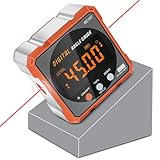
- Brilliant little cube - (Class II laser, Output<5mW) L2.4in, W2.4in, H1.2in, portable pocket size with matching belt bag. ±0.2° precise microprocessor with automatic inversion when upside down. 4*90° measurement can be used at many angles and can be zeroed at any angle for comparison.
- Craftsman's Choice - Not only the baseboard, but also the strong magnetic upgrade at the four sides. Never slide on the table saw blade or any metal surface. Magnetic feature and lasers(Class II, Output<5mW) are great advantages for measuring, cutting, leveling in woodworking renovations and building furniture.
- Save time and effort hanging decorations - Dual lasers are great helper for horizontal and symmetrical installation. Furthermore, this digital level box with slope percentage maybe a great gift for father's day, birthdays, Christmas.
- This inclinometer, digital angle finder comes complete with a USB-C charging cable for the internal 340mAH rechargeable battery. It also has dust-proof and IP67 waterproof performance with bright red backlight. Even in garage, with the door open and the sunshine pouring in, you can easily read the display.
- Technical Parameters - Material: aluminum alloy| Measuring range: 4*90°| Resolution: 0.05°| Accuracy: ±0.2°| Repeatability: 0.1°| Power supply: 3.7V lithium battery| Working temperature: 14-122℉
| Item | Value to report |
|---|---|
| Site | Address or coordinates |
| Modeled array | Number of modules and kW DC |
| Roof geometry | Tilt, azimuth and mounting type |
| Usable area | Measured roof area after access, edge and obstruction allowances |
| Shading treatment | Observed sources, modeled horizon or stated omission |
| Losses | Assumptions and whether they are generic or equipment-specific |
| Tool and data | PVWatts version/data basis and PVGIS settings |
| Output | Monthly kWh, annual kWh and any modeled variability range |
| Confidence | Preliminary, design-stage or equipment-specific, with unresolved inputs listed |
Use “average monthly kWh” when the tool reports a long-term average. Do not label it as the amount every month will deliver. Keep an annual total tied to the same modeled year basis and system assumptions.
Explain seasonality
Monthly output is normally uneven because daylight length, sun angle, cloud and temperature vary through the year. A shelter that powers lighting or bicycle charging should compare the monthly profile with the load schedule, not just the annual total. If winter service is critical, size storage or grid supply using the lower-production months rather than dividing annual kWh by 12.
Common shortcuts that produce misleading answers
- Using roof footprint as panel area: the footprint ignores access, drainage, obstructions and module geometry.
- Multiplying area by a generic kWh-per-square-metre figure: this ignores location, tilt, azimuth, shading, equipment and losses.
- Assuming a digital inclinometer calculates yield: it supplies a tilt measurement only.
- Ignoring azimuth: two arrays with the same area and tilt can have different production if they face different directions.
- Reporting nameplate capacity as annual energy: kW is instantaneous rated power; kWh is accumulated energy after weather and losses.
- Setting losses to zero: this turns a model into an unrealistic upper-bound case.
- Using one annual number: it hides the monthly pattern needed for operations and charging.
- Combining tool outputs without matching inputs: different weather databases, geometry or loss assumptions can explain the gap.
- Presenting a preliminary model as a guarantee: PVWatts itself documents inherent assumptions, uncertainty and interannual variation.
When to move beyond PVWatts
Stay with PVWatts for a first feasibility pass when the shelter location, approximate capacity and fixed geometry are known but the exact equipment is not. Move to the NLR System Advisor Model (SAM) detailed PV model when module and inverter specifications and a developed system design are available.
SAM’s detailed approach uses separate module and inverter models and can estimate temperature, shading and other losses. It is appropriate when you need to test equipment-specific behavior, stringing, inverter limits or a more developed shading and loss model. The extra detail is only useful if the design inputs are credible.
Inputs still required for a project-grade figure
Before using an output estimate to approve construction or promise energy to users, obtain:
- the shelter address or coordinates;
- roof dimensions and a measured usable module polygon;
- roof pitch and module-plane azimuth;
- a preliminary module layout and total DC nameplate capacity;
- nearby obstruction and horizon-shading information;
- mounting, module and inverter assumptions;
- defensible electrical and environmental loss assumptions; and
- structural, wind, snow, waterproofing, electrical and permit checks from the relevant professionals.
With those inputs, a location-based PVWatts case, an independent PVGIS case and—once equipment is specified—a SAM case provide a traceable estimate rather than a roof-area guess.
Quick Recap
Product prices and availability are accurate as of the date/time indicated and are subject to change. Any price and availability information displayed on Amazon at the time of purchase will apply.

