A low-voltage distribution board is an enclosed electrical assembly that receives power and distributes it to outgoing circuits. It brings switching and protective devices together so circuits can be controlled and faults can be isolated at the appropriate circuit. It is part of an electrical installation; it does not generate electricity.
How a distribution board works
Think of the board as a controlled junction between the incoming supply and the circuits serving a building. Internal distribution components feed power to outgoing circuits, while switches and protective devices provide ways to control those circuits and interrupt current under specified fault or overload conditions. Protection is not infallible, and the board alone cannot make an electrical installation safe.
The exact arrangement depends on the board design, the installation and its earthing system. A board is only one element of a wider low-voltage distribution system, which also involves equipment and wiring choices, earthing arrangements and environmental conditions. Schneider Electric’s Electrical Installation Guide discusses these considerations.
What is inside a low-voltage distribution board?
Components vary by type and application; not every board has every item in the same form. Typical features include:
Recommended Free Tools
#1 Best Overall
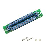
- 100% Brand new and high quality.Perfect for Railway & Building Layout!This distribution is the ideal solution for the model train to supply all lighting.
- Operation with DC/AC or digital current.2 input terminals.24 + 2 output terminals.
- Layout Wire and Lighting.For use with your scale model railroad.
- Brand:evemodel.Size:Approx.9.5cm or 3.74inch(L),1.87cm or 0.74inch(W)Max. Current via individual outputs: 10 A (observe total current).Max. External operating voltage: 24 V ~ / -
- Package included:1 Set Power Distribution Board.
- An enclosure and mounting system.
- Incoming terminals and, often, a main switch or isolator.
- Busbars or another internal arrangement for distributing incoming power.
- Outgoing circuit breakers, fuses or other protective devices.
- Neutral and protective-earth bars or terminals, as appropriate to the electrical system.
- Labels and a circuit schedule identifying the circuits served.
Hager’s Guide to IEC 61439 illustrates how assembly configurations differ, from incoming switching and busbars to modular or higher-current devices.
How main and sub-distribution boards differ
The terms describe where a board sits in the installation, rather than two interchangeable names for the same position.
Rank #2

- 2×12 Position Terminal Block : Features a 2×12 screw terminal layout with 24 connection points, making it easy to organize power or signal wiring in low-voltage electrical projects.
- 10A / 48V Low-Voltage Use :Recommended for low-voltage circuits up to 48V. While the module is ideal for car, RV, boat, LED, model railroad, and DIY wiring projects.
- Secure Screw Terminal Design :Each position uses a screw-down terminal to help keep wires firmly connected. The design makes wiring cleaner, easier to inspect, and simpler to maintain.
- Clean Power Distribution :Ideal for splitting or organizing positive and negative wiring without messy splicing. A practical solution for model train layouts, LED lighting, small electrical boxes, control panels, and DIY wiring layouts.
- Easy to Install & Expand :The compact modular board helps create a neat wiring layout and can be combined with additional modules when more connection points are needed. Suitable for both DIY users and professional installers.
| Board type | Position and role |
|---|---|
| Main switchboard | Typically receives the supply near its origin, such as in a transformer area, and feeds the wider installation. |
| Main distribution board | Receives power from the main switchboard and distributes it onward, often from a technical area. |
| Sub-distribution board | Receives a feeder from an upstream board and distributes power locally to a smaller group of circuits. |
| Consumer unit or domestic distribution board | Common terms for household-scale boards in some markets; terminology and configuration vary by country. |
Hager uses the distinctions between low-voltage main switchboards, main distribution boards and sub-distribution boards in its IEC 61439 guide. A home consumer unit is not a template for every commercial or industrial board.
What “low voltage” and the standards mean
Standards define particular equipment categories and their requirements; a scope limit for one category should not be treated as a universal limit for all low-voltage boards.
Do these 3 things before closing this tab:
1Repair Windows errors before they cause bigger problems2Scan for outdated or missing drivers - takes under a minute3Clear out junk files and repair common Windows errorsRank #3

- There are 3 connectors for the input of voltage and 2 x 10 connectors for the outputs on the distributor.
- 4 holes for mounting with wide spacers.
- Maximum voltage: 30V AC or DC voltage.
- Total supply maximum current: 8A (2-pole Power supply to terminal).
- Current carrying capacity per connection: 6A (max).
Boards intended for operation by ordinary persons
IEC 61439-3:2024, published on 26 March 2024, covers a defined category of distribution boards intended to be operated by ordinary persons (DBOs), including domestic applications. For that category, its scope includes nominal voltage to earth not exceeding 300 V AC, outgoing-circuit rated current not exceeding 125 A, and assembly rated current not exceeding 250 A. These are boundaries of the standard’s DBO scope, not general ratings for every low-voltage distribution board. IEC lists the edition’s stability date as 2028.
General low-voltage switchgear rules
IEC 60947-1:2020 provides general rules for low-voltage switchgear and controlgear when called for by the relevant product standard. Its stated circuit-rating scope does not exceed 1,000 V AC or 1,500 V DC. Those figures concern that broader switchgear and controlgear scope; they do not replace the narrower requirements for ordinary-person boards or local installation rules.
Rank #4

- 【13-Channels Dual-Pass Power Supply】The PCB power distribution board can distribute 1-channel dual-pass power supply into 13-channels dual-pass power supplies, which is convenient for the power supply of multiple electrical appliances.
- 【Three Connection Methods】The design of the power distributor can make it have three ways of use. First: directly divide the positive and negative poles of 1 channel power supply into 13 channels. Second: You can connect several PCB power distribution board to expand more power interfaces. Third: You can short-circuit any interface at both ends of the power distribution board to achieve the effect of a multi-point interface of single-pass circuit.
- 【Built-in Double-Layer Wiring】The double-layer thick wiring is used inside the PCB board, which has a better power flow effect, and there will be no poor power contact or power failure.
- 【High Quality Copper Material】The wiring terminals are made of high-quality copper pin terminals to ensure the stability and reliability of the circuit. The working voltage is 24V and the output current is 10A. It is suitable for DC and AC power distribution.
- 【Satisfaction Guarantee】High quality and customer satisfaction are our top priorities. If this product doesn’t live up your expectations, contact us and we will solve it to make sure that you are happy with your purchase.
What matters when identifying or specifying a board
The right assembly depends on the supply, loads, building, environment and applicable jurisdiction. Useful points to establish with the responsible electrical designer or contractor include:
- Whether the board is a main board or a downstream board, and where it will be installed.
- Its rated voltage and current, and the supply and earthing arrangement it must suit.
- The number and type of outgoing circuits and compatible protective devices.
- The enclosure’s suitability for the installation environment and any planned expansion.
- Whether the assembly is designed and verified for the applicable standard and installation requirements.
No single board specification can be selected responsibly from the label “low voltage” alone. The design must account for the actual installation and local electrical rules.
Best Value

- DIN Rail Mount Power Distribution Fuse Module Board.
- Work voltage: AC or DC 5~32V, total current rating 40Amp. PCB Dimensions: 150mm x 72.5mm x 29mm (W x L x H). Module Dimensions: 153mm x 87mm x 53mm (W x L x H).
- Input terminals: pitch - 7.62mm/0.3", current 30A for per position, wire size 26~10 AWG, stripping length 8mm, Metric M3 slotted screw.
- P1 output terminals: pitch - 5.08mm/0.2", maximum current 10A for per position, wire size 26~12 AWG, stripping length 7mm, Metric M2.5 slotted screw.
- P2-1 to P2-10 output terminals: pitch - 7.5mm/0.295", maximum current 10A for per position, wire size 26~12 AWG, stripping length 7mm, Metric M2.5 slotted screw.
Safety and responsibility
Distribution boards can expose people to hazardous electrical energy. Installation, modification, replacement and fault diagnosis should be performed by appropriately qualified people under the rules that apply where the building is located. A board’s devices do not replace upstream supply protection, and the board itself does not establish the installation’s earthing arrangement.
Quick Recap
Product prices and availability are accurate as of the date/time indicated and are subject to change. Any price and availability information displayed on Amazon at the time of purchase will apply.