Do these 3 things before closing this tab:
1Clear out junk files and repair common Windows errors2Scan for outdated or missing drivers - takes under a minute3Repair Windows errors before they cause bigger problemsA small voltage drop as a three-phase motor draws more current can be normal. A substantial, unequal, or rapidly worsening drop is not: it can point to a weak supply, undersized or damaged wiring, a failing connection or control device, phase imbalance, excessive mechanical load, a motor fault, or a drive problem. The fastest way to locate it is to compare all three phase-to-phase voltages at the source and motor while the motor is lightly loaded and under its normal load, then compare all three phase currents.
What voltage drop under load means
Every feeder has impedance. As motor current rises, some voltage is lost across that impedance. A simplified relationship is ΔV = I × Z. For a balanced three-phase AC circuit, a practical steady-load estimate is:
ΔV = √3 × I × (R cos φ + X sin φ) × L
Iis line current;RandXare conductor resistance and reactance per unit length;cos φis power factor; andLis one-way conductor length.- The formula helps estimate cable drop; it does not diagnose a loose lug, defective contact, weak transformer, or mechanical overload. Schneider’s guide distinguishes steady-load calculations from motor-starting conditions: steady-load voltage-drop calculation.
At no load, a motor may draw relatively little current, so a long feeder or resistive connection can appear satisfactory. Under mechanical load, current rises and the same impedance produces more drop. If terminal voltage falls enough, an induction motor may lose torque, slow, slip more, and heat up. Depending on the load and motor, it may draw still more current, creating a worsening cycle. Low voltage is not a simple fixed-current relationship: torque demand, speed, power factor, motor design, and any drive or starter control all affect what happens.
Starting drop is a separate case. Starting current is substantially higher than normal running current, so a motor can start poorly or pull down the supply even if its steady-state voltage is acceptable.
The Tool Desk
Outbyte Driver Updater FREEScan for outdated or missing drivers - takes under a minuteDriver Scan →Outbyte PC Repair FREEClear out junk files and repair common Windows errorsFree Scan →#1 Best Overall
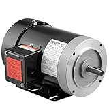
- High Performance: 1HP high-performance motor featuring 4.1 N.m rated torque. Designed for AC 230V/460V 60Hz, three-phase power. The air compressor electric motor operates at 1725 RPM for fast, reliable speed
- Rugged Frame Type: The 56C frame of this electric motor includes a 5/8-inch shaft diameter, 1.88-inch shaft length, and keyway size: 0.188 inch / 4.77 mm width x 0.094 inch / 2.38 mm depth
- Dual Rotation Direction: Our electric motor offers reversible CW/CCW rotation, simplifying wiring installation and providing quick, versatile connections for various applications
- Secure & Reliable: This air compressor motor is CSA-certified and features a rolled steel housing for dependable strength. Its improved cooling system helps reduce overheating, while a manual reset overload protector supports stable, long-term performance
- Various Applications: VEVOR general purpose motor is ideal for DIY projects and repair replacements, providing versatile and powerful functionality for water pumps, agricultural machinery, and general equipment
Locate the drop from source to motor
Compare matching phase pairs at each point—for example, source VAB with motor VAB—under the same operating condition. Record readings with the motor lightly loaded and carrying its normal load. For a useful diagnosis, check at the source or motor-control-center (MCC) terminals and then downstream through the disconnect, starter, cable, and motor terminals.
| Loaded readings | Likely direction to investigate |
|---|---|
| All three phase-to-phase voltages fall similarly at the source | Utility supply, transformer, generator, service, or upstream feeder capacity; consider other large loads or simultaneous starts. |
| Source stays stable but motor-terminal voltage falls | Branch-circuit length or size, cable condition, terminations, disconnect, fuse, breaker, contactor, or overload-relay connections. |
| One phase-to-phase reading falls more than the others | High-resistance connection, damaged fuse or contact, cable fault, uneven supply loading, or risk of single-phasing. |
| Voltage is reasonably balanced, but all phase currents are high | Excessive mechanical load, incorrect motor connection, low frequency, motor sizing, or drive configuration. |
| Voltage is balanced, but one phase current is substantially different | Possible motor winding, rotor, insulation, cable, or mechanical problem; investigate rather than relying on average current. |
| VFD input voltage looks stable but its DC bus falls under load | Possible source waveform or impedance issue, drive input or DC-bus problem, or overload. Review drive data and fault history. |
ABB lists line drop, undersized conductors, loose connections, excessive load, open phases, and improper supply among causes of low motor-terminal voltage, stalling, or failure to reach speed. See its low-voltage motor manual.
What voltage is acceptable?
Start with the motor nameplate and manufacturer documentation: rated voltage and frequency, full-load amps, service factor, connection diagram, and any stated operating range. Fluke discusses the commonly cited approximate ±10% nameplate-voltage range for induction motors, but that is not a blanket assurance that continuous operation at either extreme is harmless. Low voltage can impair starting torque and acceleration and increase heating; the actual limit depends on the motor and application. See Fluke’s motor voltage and efficiency guidance.
Do not confuse three different ideas: a motor’s operating-voltage tolerance, a circuit voltage-drop design target, and phase-voltage imbalance. They are not interchangeable. The familiar NEC figures of 3% for a branch circuit and 5% total for feeder plus branch are informational guidance for reasonable efficiency of operation, not a universal motor-failure threshold or automatically enforceable limit in every jurisdiction. The applicable code edition, local amendments, equipment instructions, and engineering requirements govern. See the NFPA 2022 NEC material.
Rank #2

- Specifications: 2HP 3 Phase operating horsepower, 1725 RPM maximum speed
- Material: The motor material of this air compressor is steel, sturdy appearance, not easily corroded
- Features: The air compressor motor has multiple cooling holes for rapid heat dissipation
- Widely applicable: The motor is suitable for most air compressors and has a high-power motor
- Stability: The motor has support, which improves its stability and extends its lifespan
Why phase imbalance matters
Equal reduction on all three phases and unequal phase voltages are different faults. Imbalance can drive a disproportionate current imbalance and heat the windings even when the average voltage appears acceptable. Fluke’s motor guidance says voltage imbalance should generally not exceed approximately 1%; treat that as a cited general limit, not a substitute for the motor’s applicable standard and manufacturer instructions. Schneider also describes voltage imbalance as a major contributor to motor overheating and premature failure, including risk at 1%: Schneider’s explanation of voltage imbalance.
Use all three phase-to-phase readings to calculate imbalance:
Average voltage = (VAB + VBC + VCA) / 3
% voltage imbalance = (largest deviation from average / average voltage) × 100
For example, readings of 475 V, 471 V, and 470 V average 472 V. The largest deviation is 3 V, so imbalance is 3 / 472 × 100 = 0.64%. This calculation is not the same as total voltage drop from source to motor.
Rank #3

- General Purpose Three Phase Motor: HP - 3,POLE - 2,FRAME -56C, ENC -TEFC,IP - 55
- Security Persistent: INS - F, Rotation - CW/CCW, Shaft diameter - 5/8",Shaft length - 1.88"
- Housing Material: Rolled steel shell. Adopt S1 continuous working system, safe and durable, long service life
- HZ: 60Hz, Voltage: 230V/460V, AMP: 9.0A / 4.5A,RPM: 3450
- Widely Application: General purpose motor is suitable for general equipment. Please purchase motor according to the specific needs of the parameters, you can send an email for detailed inquiry at any time
Fluke cites an example where 2.3% voltage unbalance produces nearly 18% current unbalance and substantial temperature rise; that is an example, not a universal conversion rule. Its materials also describe roughly 8% current imbalance in some conditions with 1% voltage imbalance. Actual response varies by motor and operating conditions. See Fluke’s imbalance and temperature example and its voltage-imbalance guidance.
Measure safely and consistently
Measurements inside energized motor-control equipment expose the worker to shock and arc-flash hazards. Energized testing should be done only by qualified personnel using appropriately rated instruments, PPE, and safe work practices. Schneider advises using PPE and a properly rated voltage-sensing device to verify de-energization before work. See its MCC troubleshooting and safety guidance. Do not open energized equipment or make live measurements unless qualified and equipped to do so.
For a three-phase motor, record the three phase-to-phase voltages VAB, VBC, and VCA. A single phase-to-neutral reading is not a substitute for checking the phase-to-phase supply to a phase-to-phase motor. Use a meter or analyzer with a suitable CAT rating and voltage range; true-RMS capability is useful for distorted waveforms. A power-quality analyzer may be needed for intermittent sags or events that occur only during startup.
- Record motor and operating data. Note nameplate voltage, frequency, current, service factor, connection diagram, speed, starter or VFD type, load type, and whether symptoms occur at startup, steady load, or both.
- Check the driven machine with power isolated. Follow lockout and verify safe condition before checking shaft movement, bearings, lubrication, belts, couplings, pump, fan, gearbox, and signs of binding or blockage. Disconnecting the load is appropriate only when the equipment manufacturer’s procedure allows it.
- Measure source voltage at light and normal load. Record all three phase pairs. A sag already present at the source points upstream; stable source voltage directs attention downstream.
- Compare voltage through the control path. A qualified technician can compare readings before and after disconnects, fuses, breaker, contactor, overload relay, cable run, and motor terminals while loaded. A drop concentrated across a closed device or connection suggests abnormal resistance.
- Measure all three line currents. Record each phase, compare with nameplate full-load amps and applicable service-factor limits, and note differences among phases. Do not rely on an average that conceals one high phase.
- Calculate voltage drop and imbalance separately. Total drop is
((source voltage − motor voltage) / source voltage) × 100using matching phase pairs. Use the average-voltage method above for imbalance. - Look for thermal evidence. An infrared scan can reveal hot fuse holders, lugs, contactor poles, cables, motor areas, or bearings. Correlate hot spots with electrical readings; a scan alone does not identify every intermittent or hidden fault.
- For a VFD, record drive data. Capture input voltage, output current, displayed DC-bus voltage, frequency, warnings and fault history, current-limit status, motor parameters, and acceleration settings. Use instruments and procedures suitable for PWM drive outputs.
For a calculated source-to-motor example, suppose one matching phase pair measures 480 V at the source and 465 V at the motor while loaded. The drop for that pair is (480 − 465) / 480 × 100 = 3.125%. Calculate the other two pairs as well: an average or single-pair result can hide an unequal phase fault.
Free tools Windows power users keep installed
One-click scans. No signup required.
Rank #4

- Three phase General Purpose Motor: HP - 5, POLE - 4, FRAME - 184T, ENC - TEFC, IP - 55, HZ: 50/60Hz, Voltage: 230V/460V, AMP: 13.42A / 6.71A, RPM: 1480/1770, INS - F, Rotation -CW/CCW, Shaft diameter - 1-1/8", Shaft length - 2.75".
- AC Motor Housing Material: Cast iron shell. Adopt S1 continuous working system. Safe and durable, long service life.
- Fully Enclosed Fan: Electric motor with large fan at one end, even in wet and dusty conditions, cools the motor during long runs, thus reducing energy costs, reducing operating temperatures and increasing service life.
- High Working Efficiency: Compact structure and small size, electric motor can run at the maximum speed of 1480/1770 rpm, high working efficiency; There are lots of heat sinks, so it has huge heat sinks.
- Widely Application: The 5hp electric motor widely used in industrial and agricultural production, transportation, commercial and household appliances and other fields. For example, water pump, agricultural machinery and so on.
Common causes and what to check
Long or undersized conductors
Drop increases with current and conductor length and is affected by conductor size and material, temperature, power factor, and reactance. A cable may meet its thermal ampacity requirement yet produce an undesirable operating or starting drop. If source voltage is stable but motor voltage is low, have the circuit checked for conductor sizing, installation conditions, and termination ratings rather than assuming larger wire is the first fix.
Loose, corroded, or damaged terminations
Check the disconnect, fuse holders, breaker and contactor terminals, overload relay, motor junction box, lugs, splices, flexible cord, and bus contacts. A poor connection can act like a small resistor: it may show little loss at idle but drop voltage and heat under load. Thermal inspection helps locate a suspect connection; electrical measurements are needed to confirm the affected section.
Failing fuse, breaker, contactor, or disconnect
A damaged fuse or contact pole can pass enough voltage at light load and fail under current. A qualified person can compare voltage before and after each device and measure across a closed contact under load; an appreciable voltage across a closed contact indicates abnormal resistance. This is energized testing, not a DIY inspection task.
Weak upstream supply or generator
If all three voltages sag at the source, investigate transformer or generator capacity, service loading, upstream feeder length, utility disturbance, and other large loads starting at the same time. Generator-fed motors deserve particular attention to source impedance and starting kVA. A branch-circuit repair will not correct a source that is already collapsing.
Best Value

- Three Phase Motor: HP - 1, POLE - 4, FRAME - 56C, ENC - TEFC, IP - 55, Voltage: 230-460V, AMP: 3.8A/1.9A , RPM: 1725, INS - CLF, Rotation - CW/CCW, Shaft diameter - 5/8", Shaft length - 1.88".
- Fully Enclosed Fan: AC Electric motor with large fan at one end, even in wet and dusty conditions, cools the motor during long runs, thus reducing energy costs, reducing operating temperatures and increasing service life.
- High Working Efficiency: Compact structure and small size, electric motor can run at the maximum speed of 1725 rpm, high working efficiency; There are lots of heat sinks, so it has huge heat sinks.
- Housing Material: Rolled steel shell. Adopt S1 continuous working system. Safe and durable, long service life.
- Widely Used: General purpose motor is suitable for general equipment. Please purchase motor according to the specific needs of the parameters, you can send an email for detailed inquiry at any time.
Open phase or single-phasing
A blown fuse, open contactor pole, broken conductor, loose terminal, failed disconnect contact, or damaged cable can interrupt one phase. Depending on load and protection, a three-phase motor may continue running while the remaining phases carry damaging current. Measure all three currents as well as voltages: voltage readings alone may not expose every single-phasing condition. Fluke emphasizes current measurement in its motor voltage and current guidance.
Excessive mechanical load
A blocked pump, excessive pump head, restricted fan, conveyor jam, tight or failed bearing, misalignment, overtensioned belt, damaged gearbox, product buildup, or changed impeller or pulley can raise current while voltage remains reasonably balanced. Check the process and driven machine, not just the electrical supply.
Incorrect motor connection or motor fault
Verify terminal links and starter configuration against the nameplate. A dual-voltage motor connected for the wrong supply voltage, an incorrect frequency, or incorrect motor data in a starter or drive can cause poor torque and excessive current. If voltage is balanced but current remains badly unbalanced, investigate winding, rotor, insulation, eccentric air gap, and cable faults with appropriate motor tests.
Soft starter or VFD issue
For a soft starter, distinguish an input supply problem from current limiting or a ramp that keeps the motor accelerating too slowly and heating. For a VFD, distinguish input sag, DC-bus loss, output-voltage limits, current limiting, configuration errors, harmonics or distorted input waveform, and mechanical overload. The drive’s PWM output is not a sine wave, so ordinary sine-wave assumptions and unsuitable meters can mislead. Schneider documents a case in which a heavily loaded drive’s DC bus falls while motor current rises despite only a small change in incoming RMS voltage: Schneider’s VFD DC-bus guidance.
Windows Errors? Fix Them Before They Spread
Repair common Windows errors and clear accumulated junk for a smoother, more stable PC - no reinstall needed.Free scan · no reinstallCrashes, No Sound, or Screen Glitches?
Random freezes, missing sound and display glitches usually trace back to one bad driver. Find and replace yours safely.Free scan · under a minuteChoose a fix that matches the measurement
- Drop across a connection or control device: repair or replace the defective termination or component using rated parts and proper procedures. Do not treat a hot connection as the only fault until source, cable, and load have also been checked.
- Motor voltage low while source stays stable: correct damaged wiring or terminations and have conductor size assessed for ampacity, voltage drop, installation conditions, protection, and termination ratings. Larger conductors help only if feeder impedance is the cause; they do not fix a bad contact or overloaded machine.
- Current high with stable, balanced voltage: reduce or correct the mechanical load, verify motor connection and frequency, and confirm the motor is suitable for the application. Reducing load may affect production, but continuing to run an overloaded motor risks damage.
- Startup sag is the main issue: a correctly selected soft starter can limit starting current and mechanical shock; a VFD may be suitable where speed control or managed acceleration is needed. Neither necessarily fixes steady-state drop, a defective feeder, a severe source limitation, or a jammed machine. Incorrect settings can prolong acceleration and heat the motor.
- Upstream voltage sags: involve the utility, generator or transformer supplier, or a qualified electrical engineer to assess source capacity, feeder impedance, load timing, and protection. A service or transformer upgrade can affect multiple loads but requires engineering and coordination.
- Alternative motor voltage is being considered: use it only if the motor nameplate supports the voltage and the motor connection, starter, protection, transformer, and other equipment are compatible. Higher distribution voltage can reduce current for the same power, but it is not accomplished by simply applying more voltage.
- Supply is proven good but imbalance or overheating remains: have the motor and cable tested and repaired or replaced as indicated.
Do not install a larger breaker as a voltage-drop remedy. Protective-device changes can defeat conductor and motor protection and require a properly engineered, code-compliant design.
When to stop and escalate
Stop operating the motor and get qualified electrical or mechanical help if a phase is missing, voltage or current imbalance is severe, the motor temperature rises rapidly, an overload trips repeatedly, there is a burning smell or arcing, or energized parts are exposed. Also escalate persistent generator or utility-side sag and recurring VFD faults after basic configuration checks. Schneider’s MCC safety guidance calls for appropriate PPE and verification of de-energization before work.
Quick Recap
Product prices and availability are accurate as of the date/time indicated and are subject to change. Any price and availability information displayed on Amazon at the time of purchase will apply.