You can build a useful two-waveform signal source on a breadboard with a 555 timer and a dual op amp. The 555 produces an adjustable rectangular waveform; an op-amp integrator converts that waveform into an approximately triangular output.
This is an educational signal generator, not a calibrated laboratory instrument. Frequency, duty cycle, amplitude, and triangle linearity depend on the exact ICs, supply, component tolerances, breadboard layout, and measurement equipment.
As an Amazon Associate I earn from qualifying purchases.
What you will build
555 astable oscillator
        │
        ├── square-wave output
        │
        └── op-amp integrator
                    │
             triangle-wave output
The 555 output is square-like, but it is not necessarily a perfect 50% square wave. The timing capacitor produces an exponential charge-and-discharge waveform. The approximately linear ramps come from integrating the 555 output with an op amp.
The Tool Desk
Outbyte PC Repair FREEClear out junk files and repair common Windows errorsFree Scan →Outbyte Driver Updater FREEScan for outdated or missing drivers - takes under a minuteDriver Scan →An RC filter alone produces a rounded, frequency-dependent waveform. It is not equivalent to a buffered active integrator.
#1 Best Overall

- Type:Accessories,
- Accessories Function:Motor,
- Model:LDTR-417995,
- Dimension(cm):7*5*2,
- Net Weight(kg):0.006,
Parts and tools
- One 8-pin 555 timer, such as an LM555 or NE555, or a CMOS alternative such as the ST TS555
- One dual op amp. A TL082 is suitable only when its supply and input/output-voltage limitations are respected.
- Breadboard and jumper wires
- Resistors, timing and feedback capacitors, and one or more potentiometers
- 100 nF ceramic bypass capacitors and a 10–100 µF bulk supply capacitor
- Regulated DC supply and multimeter
- Oscilloscope or USB test instrument
- Optional: diodes for duty-cycle adjustment and a buffer resistor at each output
How the 555 oscillator works
In astable mode, the 555 repeatedly charges and discharges a timing capacitor between approximately one-third and two-thirds of the supply voltage. Its internal comparators, flip-flop, and discharge transistor control the cycle.
For the standard astable circuit:
- RA connects from VCC to pin 7.
- RB connects from pin 7 to the joined pins 2 and 6.
- C connects from the joined pins 2 and 6 to ground.
- Pin 3 is the rectangular-wave output.
The idealized timing equations are:
tHIGH = 0.693(RA + RB)C
tLOW = 0.693RBC
f ≈ 1.44 / ((RA + 2RB)C)
D ≈ (RA + RB) / (RA + 2RB)
Here, D is the fraction of each cycle for which the output is high. Because the charging path includes both resistors while the discharge path uses RB, the basic circuit does not naturally produce an exact 50% duty cycle.
A practical 1 kHz starting point
Try:
- RA = 1 kΩ
- RB = 68 kΩ
- C = 10 nF
This gives:
f ≈ 1.44 / ((1,000 + 2 × 68,000) × 10 nF) ≈ 1.05 kHz
Do these 3 things before closing this tab:
1Fix the driver behind crashes, sound loss and screen glitches2Clear out junk files and repair common Windows errors3Scan for outdated or missing drivers - takes under a minuteThe calculated duty cycle is approximately 50.7%. The measured result will vary with capacitor tolerance, supply voltage, temperature, leakage, breadboard construction, and the particular 555 variant.
Wire the 555 stage first
For a standard 8-pin bipolar 555:
| Pin | Function | Connection |
|---|---|---|
| 1 | Ground | Supply negative |
| 2 | Trigger | Join to pin 6 and the timing-capacitor node |
| 3 | Output | Square-wave output |
| 4 | Reset | VCC when unused |
| 5 | Control voltage | Usually 10 nF to ground |
| 6 | Threshold | Join to pin 2 and the timing-capacitor node |
| 7 | Discharge | Junction of RA and RB |
| 8 | VCC | Positive supply |
Check the exact package datasheet before inserting the IC. Pin 1 is identified by a notch or dot, depending on the package. Reversing a DIP IC can destroy it or produce misleading symptoms.
Rank #2

- Minidodoca high quality 24 Values 173 Pcs IC Assortment Kit
- IC chip Assortment contains: Op Amp: LM358 LM324 JRC4558 NE5532 LM386 TDA2030 TDA2822 UA741 ;Comparators: LM393 LM339;PhotoCoupler: PC817 ;Multivibrator: CD4047;Analog Multiplexer: CD4053;Echo Audio Processor: PT2399; PWM controller: UC3842 UC3843; Darlington Array ULN2003 ULN2803;Voltage Converter 7660; Timer: NE555
- Including 3 pcs DIP8 socket, 3 pcs DIP14 socket, 3 pcs DIP16 socket, 3 pcs DIP18 socket
- Including 1pc IC Plier included for easy picking and removing IC chips
- Minidodoca ic kit Complete specifications, clear markings, easily identifiable models, sufficient quantity, durable materials, nickel plated surface, not easy to rust, ensuring a long service life.
TI recommends tying an unused reset pin to VCC rather than leaving it floating. The LM555 datasheet documents the astable arrangement and timing behavior.
Place a 100 nF ceramic capacitor close to the 555 supply pins. Add a 10–100 µF capacitor across the supply rails nearby.
Recommended Free Tools
Adding frequency adjustment
After the fixed-value circuit works, replace RB with a potentiometer used as a variable resistor. Add a fixed series resistor so the effective timing resistance cannot reach zero. A large potentiometer provides a broad range but makes precise adjustment difficult; a smaller fine-control potentiometer makes tuning easier around one frequency.
A useful arrangement is a switched capacitor range—such as 100 nF, 10 nF, and 1 nF—combined with a 100 kΩ or 1 MΩ coarse control and a 10 kΩ fine control. The referenced 2026 build describes 1 MΩ coarse and 10 kΩ fine adjustment.
Very large resistance values make leakage, dirty breadboards, capacitor leakage, and potentiometer wiring more significant. Very small values increase current through the discharge transistor and may exceed the practical limits of the circuit.
Rank #3
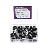
- JuForACCIC Chips Assortment Kit Specification: The Model is 555 NE555 NE555P. NE555 Timer Chip IC Pulse Generator and NE555P Single Precision Timer Functions.
- JuForACC 555 NE555 IC Assortment Kit Arguments: JuForAcc NE555P Chips Voltage is 4.5V-18V and Current: 10~15 m and Output current (maximum): 225 mA and Rise/fall time: 100 ns
- JuForACC NE555P Chips Assortment Kit Package: 1 Box includes 50 PCS NE555 Timer IC Pulse Generator ( Single Precision Timers )
- JuForACC NE555 IC Chips Application: NE555 NE555P Timer is widely used in various applications.To Make Integrated Circuit Electronic DIY Disign to control independently with two external resistors and a single external capacitor and so on.
- JuForACC AfterSale Product Services: JuForAcc will Warranty for 6 Months, we will provide return and replacement service via Amazon. If you have any issues, Immediately Contact the JuForAcc Service team and we provide 24 X 7 hours online Service.
Test the square-wave output
- Measure the supply voltage with a multimeter.
- Confirm that the 555 ground and supply negative are connected.
- Power the circuit with current limiting if available.
- Connect the oscilloscope ground clip to circuit ground only.
- Probe pin 3.
- Turn the timing control and verify that the frequency changes.
You should see a rectangular waveform whose high and low levels are related to the supply rails. If there is no oscillation, return to the fixed RA, RB, and C values before troubleshooting the potentiometer range.
Convert the square wave into a triangle wave
An ideal integrator follows:
VOUT(t) = −(1/RC) ∫ VIN(t) dt
A square wave has approximately constant positive and negative levels. Integrating those levels creates a ramp up during one half-cycle and a ramp down during the other.
Build the active integrator with an input resistor from the 555 output to the op-amp inverting input, and a capacitor from the op-amp output back to that inverting input. Ground the non-inverting input in a split-supply circuit, or connect it to a properly established midpoint reference in a single-supply circuit.
The input resistor and feedback capacitor set the integration constant. A smaller RC product produces steeper ramps and a larger triangle amplitude; a larger product produces gentler ramps and a smaller amplitude. The triangle amplitude also changes with frequency, so a simple integrator does not provide a fixed calibrated output level.
Place a large resistor in parallel with the feedback capacitor when appropriate. It provides a DC feedback path and reduces the tendency of offsets and input bias currents to charge the capacitor until the op amp saturates.
Rank #4

- Main chip: N5555; Input voltage: DC 5V-15V; Input current: ≥ 100MA; Output amplitude: 4.2V V-PPto 11.4V V-PP(Depending on the input voltage, the output amplitude will be different); Output frequency 1Hz-50Hz, 50Hz-1KHz, 1KHz-10KHz, 10KHz-200KHz Four Optional;
- There are 4 jumpers and 2 variable resistors on the module, users can adjust the output wave with these components, to get their ideal wave easily.
- Output LED indicator,: low-level LED light, high-level LED off, the frequency is low when the LED flashes.
- Capacitive capacity determines the frequency range, the user can calculate the adjustment according to their own needs.
- The output duty cycle can fine-tune. Duty cycle and frequency is not separately adjustable, adjusting the duty cycle will change the frequency.
TL082 supply limitations
The conventional TI TL082 is a dual JFET-input op amp with a typical 3 MHz gain-bandwidth product and 13 V/µs slew rate. TI lists a total supply range of approximately 7–30 V for the standard device.
Do not treat a conventional TL082 as a suitable single-5-V op amp. Its input common-mode range and output swing do not reach both supply rails. With a single 9 V supply, create a stable midpoint reference near 4.5 V—preferably buffered—and center the waveform around it. With a split supply such as approximately ±5 V or ±9 V, the integrator can operate around circuit ground more naturally.
A modern rail-to-rail op amp may be a better choice for a 5 V design, but check its exact supply range, input common-mode range, output swing, slew rate, package pinout, and output-drive capability. Pin compatibility does not guarantee electrical compatibility.
The second op-amp section
The referenced build uses the second TL082 section as a binary inverter or comparator-like stage. This is convenient because the device is already present, but an op amp used open-loop is not an ideal comparator.
An op amp may recover slowly from saturation, and its propagation delay and slew rate can distort the waveform as frequency rises. A dedicated comparator with suitable input common-mode and output-level specifications is the better upgrade, especially if the output must drive logic. Never assume that an op-amp output is automatically TTL- or CMOS-compatible.
Best Value

- TTL-Compatible Output: Features TTL-compatible output that can sink or source up to 200 mA with adjustable duty cycle for flexible circuit design
- Versatile Timing IC: NE555 is a versatile and commonly used timing IC that requires only a few resistors and capacitors to generate pulse signals of various frequencies required by digital circuits
- Technical Specifications: Pitch measures 2.54mm / 0.1 inches, line spacing approximately 8mm / 0.315 inches, 8 pins, dimensions 9 x 8 x 7mm / 0.35 x 0.3 x 0.27 inches (L*W*H)
- Operating Modes: Supports astable or monostable operation with timekeeping capabilities ranging from microseconds to hours for diverse timing applications
- Complete Package Contents: Includes 60 x NE555P pulse generator ICs and 60 x DIP-8 IC sockets for a total of 120 components
Bring up the complete circuit
- Build and test only the 555 astable oscillator.
- Use fixed timing values before adding the full potentiometer range.
- Add the 555 control-voltage bypass capacitor.
- Add supply bypassing at the op amp.
- Build the integrator separately and establish its ground or virtual-ground reference.
- Connect the 555 output to the integrator through the input resistor.
- Add the feedback capacitor and, if needed, its parallel resistor.
- Probe the integrator input and output.
- Compare the triangle amplitude at low, medium, and high frequencies.
- Add coarse and fine controls only after the fixed-value version works.
At the integrator output, expect an approximately triangular waveform over the useful operating range. At excessive frequency, the ramps may become curved or reduced in amplitude, show overshoot or asymmetry, or disappear as the op amp reaches its slew-rate, bandwidth, common-mode, or output-swing limits.
Power and measurement safety
Use a regulated supply rather than an unverified wall adapter. Keep the timing node, integrator input, and feedback wiring short. A USB instrument and a battery-powered circuit can introduce confusing ground-reference behavior.
Never connect an oscilloscope ground clip to a point that is not circuit ground unless the measurement system is specifically designed for differential measurement. A USB oscilloscope may connect circuit ground to the computer or USB ground.
An instrument such as the Digilent Analog Discovery 3 combines an oscilloscope, waveform generator, logic analyzer, and variable power supplies; its product page listed a $379 MSRP and up to 125 MS/s sampling when retrieved. It is useful for broader electronics work, but excessive for this one beginner circuit.
Troubleshooting
| Symptom | Likely causes and fixes |
|---|---|
| No oscillation | Check pins 2 and 6, pin 7, the timing capacitor, reset-to-VCC connection, IC orientation, supply voltage, and potentiometer wiring. Measure pins 2/6 and 3. |
| Frequency is far from calculated | Check capacitor units and tolerance, potentiometer value, breadboard rows, leakage, and whether the actual topology matches the equation. |
| Duty cycle is not 50% | This is normal for the basic astable circuit. Use steering diodes, a divider, or a separate comparator/logic stage if a 50% output is required. |
| Triangle is curved | Check whether you built a filter instead of an active integrator, whether the op amp is saturating, and whether the capacitor is leaky or the frequency is unsuitable. |
| Triangle amplitude changes with frequency | This is expected in a simple integrator. The ramp slope and time per half-cycle both change with frequency. |
| Op amp sticks to a rail | Check the TL082 supply voltage, input common-mode range, virtual-ground reference, DC feedback path, capacitor wiring, and output load. |
| Waveform is noisy | Shorten wires, add local bypass capacitors, improve grounding, use a short probe ground connection, reduce excessive resistance, and avoid driving a low-impedance load directly. |
Useful upgrades
- Better duty-cycle control: Add steering diodes so charging and discharging use separate resistances.
- Cleaner switching: Replace the op-amp inverter with a suitable comparator.
- Low-voltage operation: Use a CMOS 555 and an op amp explicitly rated for the chosen supply.
- More useful frequency range: Switch timing capacitors instead of relying on one very large potentiometer.
- Safer external connections: Add output resistors or buffers before connecting to other equipment.
- More advanced waveforms: Add a sine-wave-shaping stage, recognizing that this requires additional calibration and filtering.
Realistic performance limits
This breadboard circuit is suitable for learning about timers, RC timing, integration, op-amp limitations, and oscilloscope measurements. It is not intended for precision frequency synthesis, calibrated amplitude output, high-frequency laboratory work, direct 50 Ω loads, or high-voltage and mains applications.
The design described in the 2026 Hackaday build is a useful starting concept: a 555 astable oscillator, a TL082 integrator, and a second op-amp section used as a binary inverter. Building the stages separately and measuring each node makes the circuit more understandable—and much easier to repair when the triangle output is not yet triangular.
Quick Recap
Product prices and availability are accurate as of the date/time indicated and are subject to change. Any price and availability information displayed on Amazon at the time of purchase will apply.
What’s actually slowing this PC down?
Pick the symptom - the matching free tool is one click away.

