Some links on this page are affiliate links: if you buy through them we may earn a commission, at no extra cost to you.
You can build a useful relative vibration meter with an Arduino-compatible board and an ADXL345 three-axis accelerometer. The meter measures dynamic acceleration, removes the sensor’s static gravity component, and reports one-second RMS and peak values in g. It is suitable for comparing a fan, motor, pump, appliance, or 3D printer under consistent conditions—not for certified machine-condition diagnosis.
What the meter measures
An accelerometer always measures gravity as well as movement. A stationary sensor therefore reads about 9.81 m/s² (1 g) on the axis pointing upward. The project below estimates dynamic acceleration by tracking a slow baseline on each axis, then calculates the RMS and peak magnitude over a fixed sample window.
- RMS acceleration: useful for comparing steady operating conditions.
- Peak acceleration: highlights impacts and intermittent shocks.
- Frequency: not measured by the basic sketch; reliable frequency analysis requires controlled, timestamped sampling and an FFT.
The result is a relative vibration indication. It is not a calibrated velocity or displacement measurement, an ISO severity classification, or proof of bearing failure.
What’s actually slowing this PC down?
Pick the symptom - the matching free tool is one click away.
Parts and sensor choice
- Arduino Uno, Nano, Micro, or another board with an Arduino-compatible core.
- ADXL345 digital three-axis accelerometer breakout.
- USB cable, breadboard, and jumper wires for initial testing.
- Rigid mounting hardware: screws, adhesive pad, wax, or a magnetic mount.
- Optional OLED display, buzzer or LED, battery, enclosure, and microSD card.
The ADXL345 offers selectable ±2 g, ±4 g, ±8 g, and ±16 g ranges, selectable output data rates, a 32-level FIFO, and I²C or SPI interfaces (Analog Devices product page). Start with ±2 g when the signal is small; select a higher range if the waveform clips.
#1 Best Overall

- This Ceramic Piezo Vibration Piece Sensor buffers a piezoelectric transducer that responds to strain changes by generating a measurable output voltage change which is proportional with the strength of vibration. So you can know the extent of vibration. Different from digital vibration sensor that only accounts times, this analog one can tell extent of vibration.
- Based on piezoelectric ceramic chip analog vibration makes use of the anti-transformation process of piezoelectric ceramic making the electric signals vibrate.
- Working Voltage: 3.3V or 5V. Working Current: 1mA. Interface Type: Analog Output.
- When the piezoelectric ceramic shocking will generate an electrical signal, Controller analog port can be perceived slight vibration signals, Also can be realized with vibration interactions related works, such as electronic drums.
- Analog Ceramic Piezo Vibration Sensor Module 3.3V/5V for Arduino DIY Kit
Check the breakout’s voltage design
The bare ADXL345 operates from 2.0–3.6 V and its I/O supply is 1.7 V to VS (datasheet). A regulated, level-shifted breakout is easier with a 5 V Arduino. Adafruit’s board accepts the documented VIN and I²C connections for 3 V or 5 V microcontrollers (wiring guide). Do not connect 5 V to a bare 3.3 V module.
Wire it over I²C
| ADXL345 breakout | Arduino Uno-style board |
|---|---|
| VIN or 3V/3.3V, as specified by the breakout | Appropriate regulated supply |
| GND | GND |
| SDA | SDA / A4 |
| SCL | SCL / A5 |
The commonly documented breakout address is 0x53 (Adafruit wiring guide). SDA and SCL pins differ on other Arduino boards, so check that board’s documentation. Keep the sensor and wiring mechanically secure; loose jumpers can measure their own movement.
Install the Arduino library
- Open Tools → Manage Libraries in Arduino IDE.
- Search for Adafruit ADXL345 and install it.
- Install the prompted Adafruit Unified Sensor dependency.
- Open File → Examples → Adafruit ADXL345 → sensortest.
- Select your board and port, compile, and upload.
The library provides initialization, range and data-rate selection, and X/Y/Z readings (library reference).
Rank #2

- 5pcs SW-420 Motion Sensor Module Vibration Sensor Vibration Switch Alarm Sensor for Arduino
- The working voltage of 3.3V to 5V
- Output form: digital switch output (0 and 1)
- Small board PCB size: 3.2cm x 1.4cm
- Product vibration, the vibration switch instantaneous disconnection, output the output high level, the green light is not bright;
Verify the sensor with a raw-data sketch
#include <Wire.h>
#include <Adafruit_Sensor.h>
#include <Adafruit_ADXL345_U.h>

Adafruit_ADXL345_Unified accel = Adafruit_ADXL345_Unified(12345);

void setup() {
  Serial.begin(115200);
  if (!accel.begin()) {
    Serial.println("ADXL345 not detected. Check power, SDA, SCL, and address.");
    while (true) delay(100);
  }
  accel.setRange(ADXL345_RANGE_2_G);
  accel.setDataRate(ADXL345_DATARATE_100_HZ);
  Serial.println("ADXL345 ready");
}

void loop() {
  sensors_event_t event;
  accel.getEvent(&event);
  Serial.print("X: "); Serial.print(event.acceleration.x);
  Serial.print(" m/s^2, Y: "); Serial.print(event.acceleration.y);
  Serial.print(" m/s^2, Z: "); Serial.print(event.acceleration.z);
  Serial.println(" m/s^2");
  delay(10);
}
With the board still, one axis should normally be near ±9.81 m/s². Rotate the board and the gravity component should move to another axis. Tapping or shaking it should create transients. That stationary 1 g reading is gravity, not vibration.
Upload the RMS vibration meter
This sketch tracks a slow per-axis baseline, subtracts it from each sample, and calculates dynamic RMS and peak magnitude over 100 samples. The nominal sensor data rate is 100 Hz and the intended interval is about 10 ms; loop overhead means the effective acquisition rate is not guaranteed.
#include <Wire.h>
#include <Adafruit_Sensor.h>
#include <Adafruit_ADXL345_U.h>

Adafruit_ADXL345_Unified accel = Adafruit_ADXL345_Unified(12345);
const int WINDOW_SAMPLES = 100;
const float alpha = 0.02;
float baselineX, baselineY, baselineZ;

void readAcceleration(float &x, float &y, float &z) {
  sensors_event_t event;
  accel.getEvent(&event);
  x = event.acceleration.x; y = event.acceleration.y; z = event.acceleration.z;
}

void setup() {
  Serial.begin(115200);
  if (!accel.begin()) {
    Serial.println("ERROR: ADXL345 not detected.");
    while (true) delay(100);
  }
  accel.setRange(ADXL345_RANGE_2_G);
  accel.setDataRate(ADXL345_DATARATE_100_HZ);
  readAcceleration(baselineX, baselineY, baselineZ);
  Serial.println("Keep the sensor still for the first few seconds.");
}

void loop() {
  float sumSquares = 0.0, peak = 0.0;
  for (int i = 0; i < WINDOW_SAMPLES; i++) {
    float x, y, z;
    readAcceleration(x, y, z);
    baselineX += alpha * (x - baselineX);
    baselineY += alpha * (y - baselineY);
    baselineZ += alpha * (z - baselineZ);
    float dx = x - baselineX, dy = y - baselineY, dz = z - baselineZ;
    float dynamicMagnitude = sqrt(dx * dx + dy * dy + dz * dz);
    sumSquares += dynamicMagnitude * dynamicMagnitude;
    if (dynamicMagnitude > peak) peak = dynamicMagnitude;
    delay(10);
  }
  float rms = sqrt(sumSquares / WINDOW_SAMPLES);
  Serial.print("RMS: "); Serial.print(rms, 3);
  Serial.print(" m/s^2 ("); Serial.print(rms / 9.80665, 4);
  Serial.print(" g), Peak: "); Serial.print(peak / 9.80665, 4);
  Serial.println(" g");
}
The printed RMS is dynamic acceleration magnitude over the one-second window. It is not automatically an industrial “vibration level.” The baseline coefficient is a practical starting point, not a universal filter specification.
Rank #3

- Output format: Digital switching output (0 and 1)
- Working voltage 3.3V-5V
- With a wide voltage LM393 comparator
Mount and validate it
Mounting
Attach the sensor firmly at the measurement point. A loose board, rattling enclosure, or moving USB cable can create a larger signal than the machine. For severe shock or vibration, use locking connectors or direct soldering as recommended by Adafruit’s assembly guidance. Power down equipment before mounting wherever possible and keep electronics clear of rotating parts, heat, oil, water, and energized conductors.
The Tool Desk
Outbyte PC Repair FREERepair Windows errors before they cause bigger problemsFix Now →Outbyte Driver Updater FREEScan for outdated or missing drivers - takes under a minuteDriver Scan →Sanity check and repeatability
- Leave the powered sensor stationary for several seconds.
- Record X, Y, and Z and confirm the vector magnitude is approximately 1 g.
- Rotate it through several orientations; gravity should change axes without producing real vibration.
- Tap the mounting surface and confirm a transient response.
- Run the same machine condition at least three times with identical location, orientation, mounting pressure, cable routing, and window length.
Use repeated measurements to establish a baseline for that particular machine. Do not apply a generic alarm threshold to every fan, motor, pump, or printer.
Optional output and logging
Serial Plotter
For waveform diagnosis, print tab-separated dynamic axes:
Rank #4
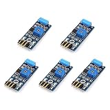
- Hiletgo SW-420 Vibration Sensor Module
- Output format: Digital switching output (0 and 1)
- Working voltage 3.3V-5V
- With a wide voltage LM393 comparator
Serial.print(dx); Serial.print('t');
Serial.print(dy); Serial.print('t');
Serial.println(dz);
Serial Plotter behavior and menu labels vary by Arduino IDE version; use the plotting tool available in your installed IDE. The general Serial Plotter workflow is described by Adafruit.
OLED, alarm, or SD card
A 128×64 I²C OLED can show RMS, peak, dominant axis, window length, and a user-established warning status. It may share the I²C bus if its address differs from the accelerometer; scan the bus if either device disappears. Add an SD card only after the live measurement is stable.
Do these 3 things before closing this tab:
1Fix the driver behind crashes, sound loss and screen glitches2Clear out junk files and repair common Windows errors3Scan for outdated or missing drivers - takes under a minuteUnderstand sampling limits
The ADXL345 library documents selectable rates from 0.10 Hz to 3,200 Hz and notes greater noise above 100 Hz and greater temperature sensitivity at very low rates (library reference). A nominal 100 Hz setting does not prove that a `delay(10)` loop acquires evenly spaced samples. Sensor reads, serial output, interrupts, and loop overhead add time.
Best Value
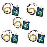
- 1. Based on piezoelectric ceramic chip analog vibration makes use of the anti-transformation process of piezoelectric ceramic making the electric signals vibrate.
- 2. When the piezoelectric ceramic shocking will generate an electrical signal, Controller analog port can be perceived slight vibration signals, Also can be realized with vibration interactions related works, such as electronic drums.
- 3. Working Voltage: 3.3V or 5V
- 4. Item Size: 30mm x 23mm
Signals above half the effective sample rate can alias into false lower frequencies. For frequency work, use data-ready interrupts, timestamps, a timer, FIFO acquisition, or a faster controller. A one-second, genuinely 100-sample-per-second record has about 1 Hz nominal FFT bin spacing; it is not suitable for high-frequency bearing or gear analysis. Analog Devices also documents communication constraints at high output rates (technical document).
Choosing alternatives and upgrades
| Option | Advantages | Limitations |
|---|---|---|
| ADXL345 | Dedicated accelerometer, selectable ranges, I²C/SPI, simple libraries | Consumer MEMS behavior, variable breakout quality, limited hobby-system timing |
| MPU-6050 | Inexpensive, common, includes gyroscope | Gyroscope is unnecessary for this meter; module voltage handling varies |
| Analog accelerometer | Direct ADC sampling can be flexible | Depends on ADC reference, resolution, analog noise, wiring, and timing |
| SPI acquisition | Higher throughput and fewer I²C timing uncertainties | More wires and more setup |
The Arduino Library Manager lists an MPU-6050 library (version 1.4.5, listed release date July 8, 2026) at Arduino documentation. Its gyroscope does not inherently improve acceleration accuracy. Upgrade to SPI, data-ready interrupts, timestamped logging, FFT processing, or a wider-bandwidth accelerometer when you need spectral or high-frequency analysis.
Troubleshooting
- Not detected: check common ground, board-specific SDA/SCL pins, VIN versus 3.3 V requirements, solder joints, address conflicts, and whether the module is actually an ADXL345. An I²C scanner is a useful next test.
- Constant 1 g interpreted as vibration: rotate the stationary board and verify that gravity merely changes axes.
- Noisy or implausibly high readings: rigidly mount the sensor, secure cables, inspect connectors, and check for a resonant enclosure.
- Clipped waveform: increase the selected range from ±2 g to ±4 g or ±8 g; clipping makes RMS and peak values too low.
- Slow drift: allow startup settling and account for temperature and baseline-filter behavior.
- Unexpected low-frequency waveform: suspect aliasing, uneven timing, moving cables, or sensor orientation changes.
When this project is not enough
Use a calibrated handheld vibration meter or a documented data-acquisition system when results will determine maintenance, acceptance, warranty, safety, or compliance decisions. Such instruments may provide calibrated acceleration, velocity and displacement modes, frequency ranges, memory, and rugged mounting. A hobby breakout can reveal changes and trends, but it cannot by itself diagnose bearings, certify equipment, or replace a standards-compliant measurement chain.
Free tools Windows power users keep installed
One-click scans. No signup required.
Quick Recap
Product prices and availability are accurate as of the date/time indicated and are subject to change. Any price and availability information displayed on Amazon at the time of purchase will apply.


Leave a Reply