Some links on this page are affiliate links: if you buy through them we may earn a commission, at no extra cost to you.
You can build an effective copper-wire antenna, but there is no universal wire length: dimensions depend on the frequency and antenna design. For a straightforward single-band HF project, a center-fed half-wave dipole is a practical starting point. Cut two equal wire legs, connect them to coax at the center, hang them safely, then measure and tune the antenna in its final position.
Choose a design for your frequency and use
A copper wire by itself is not a complete, all-purpose antenna. Its length, shape, height, feed method, and surroundings affect how it works. Start by identifying the frequency and whether you want to transmit or receive.
| Goal | Good starting design | Trade-off |
|---|---|---|
| One HF amateur-radio band | Center-fed half-wave dipole | Usually optimized for a limited frequency range. |
| Several HF bands and a suitable tuner | Multiband dipole with ladder line, or a random wire | More involved feed and matching; a tuner may not match every band. |
| Portable setup or only one practical high support | End-fed half-wave antenna (EFHW) | Normally needs a correctly designed high-impedance transformer. |
| Shortwave receive-only listening | Random wire or dipole | Noise, placement, and counterpoise or ground arrangements can matter. |
| Handheld, VHF/UHF, or 915 MHz equipment | A frequency-specific quarter-wave, ground plane, J-pole, or collinear design | HF dipole dimensions do not apply. |
| Directional reception or transmission | Loop, beam, or directional array | More complex construction and support. |
The build below is for a single-band, center-fed HF dipole. For an end-fed or multiband design, use a design and matching system intended for that purpose rather than simply moving the feed point or adding a tuner.
Do these 3 things before closing this tab:
1Repair Windows errors before they cause bigger problems2Scan for outdated or missing drivers - takes under a minute3Clear out junk files and repair common Windows errorsMaterials and tools
- Stranded copper antenna wire, long enough for both legs plus trimming allowance. Insulated 16–18 AWG wire is a practical choice for a temporary or portable build; for a permanent outdoor installation, prioritize UV resistance, strength, and weather durability.
- A center insulator or purpose-built dipole center connector, and two end insulators.
- Coaxial cable and connectors compatible with your radio and installation.
- Nonconductive support rope or UV-resistant cord.
- Wire cutters, measuring tape, and a soldering iron and solder if making soldered connections.
- Heat-shrink tubing or suitable outdoor sealing materials for exposed connections.
- An SWR meter, antenna analyzer, or VNA for checking the antenna. A basic meter is enough to check selected frequencies; an analyzer can show a frequency sweep.
- Optional: a 1:1 current choke at the feed point to help reduce unwanted current on the outside of the coax.
ARRL lists wire, center and end insulators, coax, and support rope among the core components for a basic dipole. Its particular projects specify particular wire and feed arrangements, so no one gauge or balun requirement applies to every dipole. See ARRL’s single-band dipole guidance and its classic dipole project.
#1 Best Overall

- Dipole set includes 1x dipole base with 60cm RG174, 2x 23cm to 1m telescopic antenna, 2x 5cm to 13cm telescopic antenna, 1x 3m RG173 extension cable, 1x flex tripod mount, 1x suction cup mount.
Do not use household electrical wiring that is still connected to mains circuits. Avoid relying on ordinary lamp cord as a permanent outdoor antenna. Bare wire is easy to terminate but presents contact and corrosion concerns; insulated wire is easier to handle, though its electrical behavior can differ slightly. Either way, tune the antenna after installation.
Calculate the starting length
For a half-wave dipole, a common approximate starting formula is:
Total length in feet = 468 ÷ frequency in MHz
Divide the total by two to find the approximate length of each leg. The formula is a starting estimate, not an exact finished dimension. Cut about six inches longer overall than the calculated total so you have room to tune by trimming. This formula and the need to trim are described in ARRL’s dipole guide.
Rank #2
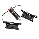
- Frequency: 5-50MHz
- SWR: ≤1.5
- Impedance: 50 Ω,SL-16
- Power: 100W PEP
- Work Length: 50MHz - 2.1m, 28(29)MHz - 4.2m, 24MHz - 5m, 21MHz -6.2m, 18MHz - 7.4m, 14MHz - 9.4m, 10MHz - 13.4m, 7MHz - 19.4m, 5MHz - 25.8m (length with extended left and right arms)
| Target frequency | Approximate total length | Approximate length per leg |
|---|---|---|
| 3.7 MHz | 126.5 ft | 63.2 ft |
| 7.1 MHz | 65.9 ft | 32.9 ft |
| 14.2 MHz | 33.0 ft | 16.5 ft |
| 21.2 MHz | 22.1 ft | 11.0 ft |
| 28.4 MHz | 16.5 ft | 8.2 ft |
For example, at 14.2 MHz, 468 ÷ 14.2 is about 32.96 feet total, or about 16.48 feet per leg before adding your trimming allowance. Actual resonance shifts with wire diameter and insulation, height above ground, soil, nearby buildings or metal, feed-line routing, and whether the antenna is straight, sloped, or bent.
Build the center-fed dipole
- Choose the frequency. Pick the frequency where you want the lowest SWR. If you use a portion of a band, choose a point near the middle of your usual operating range; one dipole may not have a low SWR across the entire band.
- Measure and cut two equal legs. Calculate the total length, add trimming allowance overall, divide it into two equal lengths, and cut one wire for each side. Keep them equal as you build and tune.
- Make the center connection. Secure one leg to the coax center conductor and the other to the coax shield at the center insulator. Keep the legs electrically separate. Provide strain relief so the wire, wind load, and cable weight are not hanging from a solder joint or connector. Weather-seal outdoor connections.
- Fit end insulators. Attach one insulator to the outer end of each leg, then tie support rope to the insulators. Rounded or looped wire ends are safer than exposed sharp tips.
- Check the feed system. A dipole is balanced; coax is unbalanced. A 1:1 current choke at the feed point can reduce common-mode current on the outside of the coax and make the installation less sensitive to feed-line routing. It is a useful option, not a universal prerequisite. If the coax itself carries significant current, moving it can change the SWR or bring RF into the operating area.
wire leg ── end insulator ── center feed ── end insulator ── wire leg
                                  │
                             coax to radio
Hang it securely
A dipole can be installed as a flat top, inverted V, slope, or bent wire when space is limited. Get it as high and clear as practical, keep the two legs separated, and mechanically support the feed point. Use nonconductive rope and leave enough slack for wind and temperature changes. Do not let coax or antenna wire carry the full pull of the supports.
- Keep the wire clear of metal gutters, fences, roofs, and power wiring; avoid running it parallel and close to conductive objects.
- Where practical, route coax away from the antenna at roughly a right angle for a short distance before taking it toward the radio.
- Measure and tune the antenna in its final position. A dipole on the ground or in a different shape can behave differently from the installed version.
Measure and tune
Disconnect or reduce transmitter power as appropriate for your equipment, and measure with an analyzer, VNA, or SWR meter according to its instructions. With an analyzer or VNA, connect at the antenna feed point where possible and sweep across frequencies around your target. With an SWR meter, take readings below, at, and above the target frequency. An analyzer sweep shows where the SWR minimum falls; see ARRL’s overview of antenna-system analysis.
Rank #3

- 8-Band Coverage & Low SWR: Operates on 80m–10m bands using a high-efficiency 1:64 impedance transformer and 40 m radiating element, delivering consistently low SWR and stable performance without constant tuning. This half-wave end-fed design provides stronger transmit and receive signals than many loaded dipole or compact vertical antennas, ideal for DX communication, amateur radio operation, and shortwave listening
- No Tuning Required: Handles SSB up to 150W, CW up to 120W and FT8 up to 80W for reliable HF operation. The integrated 1:49 / 1:64 impedance transformer enables efficient multi-band performance without an external antenna tuner in most setups, simplifying installation and helping both beginners and experienced ham operators get on the air quickly
- Flexible Hanging: This end-fed antenna enables quick, discreet installation in diverse environments. For optimal performance, keep it 3m (9.8ft) from obstacles and 5m (16.4ft) from metal surfaces. It can be mounted horizontally, vertically or diagonally with flexible balun placement, perfect for field work, home stations, backyard setups and long-term outdoor use. Its single-wire design allows fast setup between trees, poles, rooftops or masts with minimal tension
- Rugged & Weather-Resistant Design: Built with a durable ABS housing and heavy-gauge antenna wire, reinforced end insulator, and secure clamping system for reliable performance in harsh outdoor conditions. Ideal for home stations, portable setups, POTA/SOTA, camping, and emergency communication. For best longevity, inspect the installation and guy rope every 6 months (typical service life 3–5 years)
- Innovative Natural Cooling Design (GOOZEEZOO Exclusive):Built for long-term outdoor operation, the antenna features a waterproof M-J connector, UV-resistant housing, and large ferrite magnetic core (63×38×14.55 mm) for stable impedance transformation. The air-convection cooling enclosure draws cool air from the bottom and releases heat from the top, helping maintain stable performance during extended transmissions
- If the lowest-SWR point is below your target frequency, the antenna is too long: trim a small, equal amount from both ends.
- If the lowest-SWR point is above your target frequency, the antenna is too short: add wire to both ends or fold unused wire back along each end to increase its effective length.
Make small changes and measure again after each one. Do not cut to the calculated length all at once or tune based on a single reading at an arbitrary frequency. A practical dipole does not have to show 1:1 SWR across a whole band; the lowest SWR is usually near the chosen center frequency and rises toward the band edges. ARRL notes that a reading around 1.5:1 or lower near the center can be a realistic result, depending on the installation. Follow your radio manufacturer’s limits for acceptable SWR and power.
Quick wins for a faster PC:
Clear out junk files and repair common Windows errorsFree Scan →Fix the driver behind crashes, sound loss and screen glitchesFind Drivers →Repair Windows errors before they cause bigger problemsFix Now →Resonance, SWR, and efficiency are related but different. Resonance means the antenna’s reactance is near zero; SWR describes the match between the antenna system and feed line. Neither a low SWR nor a tuner’s “match” indication proves that most transmitter power is being radiated. A tuner can help the transmitter see a match without making an inefficient antenna efficient.
Troubleshoot common problems
| Symptom | Likely causes and next steps |
|---|---|
| High SWR across the band | Inspect the center connection for an open or a short between coax conductors; check the wire, connector termination, and coax. Verify dimensions and measure at the antenna feed point if possible. |
| SWR minimum is below the target frequency | The antenna is electrically too long. Trim both legs by small, equal amounts and re-measure. |
| SWR minimum is above the target frequency | The antenna is electrically too short. Add wire to both ends or fold wire back along the ends, then re-measure. |
| SWR changes when the coax is moved | Common-mode current may be making the coax part of the radiating system. Check the feed-point connection, coax route, and whether a suitable current choke is needed. |
| A tuner cannot match a random wire or multiband antenna | The wire length may be an unfavorable electrical length on that band, the tuner may not cover the impedance, or the feed line or counterpoise arrangement may be unsuitable. A tuner will not match every wire on every band. See ARRL’s notes on random wires. |
| Good SWR but weak reception or transmission | Check height, clearance, terrain or building obstruction, antenna design for the frequency, feed-line losses, and grounding where relevant. Low SWR alone does not establish good radiation or reception. |
| Excessive noise or RF in the operating area | Check local electrical noise, feed-line routing, common-mode current, and the antenna’s proximity to household wiring or equipment. Stop transmitting before touching or adjusting any antenna component. |
If the antenna tunes differently after it is raised, that is not necessarily a fault: height, shape, nearby objects, ground conditions, and feed-line routing all affect it. Retune in its installed configuration.
Rank #4

- 10 Meter Dipole 1/2 Wave Base Station Antenna
- For Amateur Ham
- Weather Tight Indoor Outdoor Design
- The Best New and Improved dipole Antenna
When another wire-antenna design makes sense
End-fed half-wave
An EFHW feeds a half-wave-length wire at one end. Its feed-point impedance is much higher than the roughly 50 ohms expected by most transceivers, so a transformer or matching network is normally required. ARRL’s example uses a 49:1 transformer for an approximate 2,500-ohm feed-point impedance. An EFHW can suit portable setups or a site with one useful high support, but the transformer must suit the frequency and power, and the end and transformer must be kept away from people during transmission. See ARRL’s EFHW reference.
Random wire
A random wire is chosen to fit available space and used with a suitable tuner; it is not necessarily a quarter-wave. Some lengths will not match well on particular bands, and the tuner’s ground or counterpoise connection is part of the antenna system. Long exposed conductors can also present an RF-burn hazard at transmitting power. See ARRL’s random-wire guidance.
The Tool Desk
Outbyte Driver Updater FREEFix the driver behind crashes, sound loss and screen glitchesFind Drivers →Outbyte PC Repair FREERepair Windows errors before they cause bigger problemsFix Now →Multiband dipole
A multiband dipole can use two equal wire lengths and ladder line with a compatible balanced tuner or matching system. Ladder line can have low loss on HF even with a high SWR, but it must be routed away from metal and conductive structures. A longer design may work on many bands, while a shorter one may not load on every band; it is not simply a single-band dipole with a tuner added. See ARRL’s multiband dipole overview.
Best Value

- HF & 6M COVERAGE Supports amateur radio operation from 1.8–50 MHz with compatible equipment across HF and the 6-meter band.
- COMPLETE PORTABLE ANTENNA KIT Includes a 1.8 MHz loading coil, 50 MHz whip, M10 telescopic whip, and PL-259 connector for portable antenna setups.
- SEGMENTED M10 TELESCOPIC WHIP The 228 cm modular whip assembles quickly and separates into compact sections for transport and storage.
- BUILT FOR PORTABLE OPERATION Suitable for POTA, SOTA, Field Day, camping, emergency communication exercises, and portable amateur radio operation.
- UP TO 200 W POWER RATING Rated for up to 200 W under specified operating conditions. Performance depends on installation, matching, grounding, operating frequency, and surrounding environment.
Loop or VHF/UHF design
A full-wave loop needs roughly one wavelength of wire and several support points; feed impedance and pattern depend on its geometry. At VHF, UHF, or 915 MHz, use a design calculated for that frequency rather than adapting the HF dimensions. The ARRL Antenna Book covers dipoles, monopoles, loops, transmission lines, construction, and measurement.
Safety before installation or transmission
- Power lines: Never raise, install, or retrieve an antenna where it could contact overhead electrical conductors. If there is any chance a wire or support could fall onto a line, choose another location. Review ARRL’s electrical-safety guidance.
- Lightning and static: A permanent outdoor installation needs an appropriate disconnect, grounding, bonding, and lightning-protection plan. A ground rod alone does not make an antenna lightning-proof.
- RF exposure: Keep people away from radiating elements while transmitting; do not touch antenna wire, exposed ends, or an EFHW transformer during transmission. Operators must follow applicable RF-exposure requirements for their service and location. In the United States, amateur stations are subject to RF-exposure evaluation requirements; consult ARRL’s RF-exposure information and its calculator.
- Work only with RF off: Do not adjust, repair, or handle the antenna while transmitting. Follow equipment and installation guidance for disconnecting power before work.
- Wire ends and supports: Use end insulators or rounded loops, keep tensioned wire out of walkways, and make supports visible and secure. Sharp wire ends can injure people.
- Operating authority: Building or receiving with an antenna is different from transmitting. Licensing and operating rules depend on the radio service and jurisdiction; check the rules for amateur, CB, GMRS, or other service before transmitting.
For a beginner building one HF antenna, the center-fed dipole is a sound first project: it needs only two equal wire legs, a simple center connection, and careful installation. The calculated length gets you close; safe support and measured, incremental tuning make it usable.
Quick Recap
Product prices and availability are accurate as of the date/time indicated and are subject to change. Any price and availability information displayed on Amazon at the time of purchase will apply.
Recommended Free Tools


Leave a Reply