Some links on this page are affiliate links: if you buy through them we may earn a commission, at no extra cost to you.
Yes, you can build a Segway-style vehicle at home—but a rideable version is a serious robotics, fabrication, electrical, and safety-engineering project, not simply an Arduino build. The practical route is to begin with a small, unrideable balancing prototype, validate the control system and drivetrain, and only then consider a slow, restrained rideable machine.
In this context, “home-made Segway” means a DIY two-wheel, self-balancing electric scooter. It does not mean a product manufactured by Segway. A home build should be treated as an experimental personal transporter unless it has undergone substantially more engineering and testing than most hobby projects receive.
What a home-made Segway actually is
A DIY Segway-style vehicle uses two independently driven wheels on a common axle, a rigid platform for the rider, a control column or handlebar, an inertial measurement unit (IMU), and a real-time controller. The controller continually detects whether the platform is tipping and commands the wheels to move underneath it.
That makes it different from:
- a small self-balancing robot, which carries no rider and stores much less energy;
- a hoverboard, which is a related but usually smaller two-wheel platform with different controls and packaging;
- a powered wheelchair or mobility scooter, which normally remains statically stable and does not balance as an inverted pendulum; and
- a commercial Segway Personal Transporter, which has production engineering, protective systems, testing, and support that a home build generally lacks.
Use “Segway-style” or “self-balancing scooter” when describing a DIY machine rather than implying that it is a genuine Segway product.
#1 Best Overall

- Speed & Range: Experience exhilarating rides with the Ninebot S2's impressive top speed of 11.2 mph and range of 21.7 miles.
- Beginner-Friendly: Perfect for riders aged 16-50, the Segway S2 features a user-friendly learning mode, providing a smooth and gradual introduction.
- Adjustable & Supportive: Enjoy a customized fit tailored to your needs, as the Segway S2 accommodates heights ranging from 4'3" to 6'6" and supports weights of up to 220 lbs, ensuring comfort and stability for every rider.
- Hill Conqueror: Conquer inclines with confidence as the Segway S2 effortlessly navigates 15° slopes.
- Efficient Charging: Featuring a Smart Battery Management System (BMS) and a high-capacity 335 Wh battery that fully charges in just 4.5 hours.
Is building one at home practical?
| Build type | Practicality | Primary concern |
|---|---|---|
| Bench-top balancing robot | High | Control tuning and mechanical alignment |
| Small unrideable prototype | Moderate to high | Sensor, motor, and software integration |
| Slow, tethered rideable prototype | Moderate | Falls, unintended acceleration, and braking |
| Full-size road-going transporter | Low for beginners | High-energy mechanical, electrical, legal, and insurance risks |
Published projects show that the concept is feasible. One documented build used wheelchair motors, a 24-volt battery system, an Arduino, an IMU, a Sabertooth motor controller, a Kalman filter, and PID control. The builder also documented safety interlocks and a startup fault that briefly caused uncontrolled motor activation; the project should therefore be read as valuable experimental documentation, not as a certified design. See the historical build documentation.
An educational workshop design used 350 W brushed DC motors with planetary gearheads, inertial sensing at 100 measurements per second, and a vehicle weighing roughly 50 pounds. Its published cost was under $1,000 at the time, while other historical projects reported figures around $500 or $800. Those are historical project estimates, not dependable 2026 budgets. Read the educational project paper.
The physics: a two-wheeled inverted pendulum
A standing rider and chassis form an inverted pendulum: the center of mass is above the wheel axle, so gravity continually tries to make the system fall. The wheels must move in the direction of the fall quickly enough to keep the axle underneath the combined center of mass.
Do these 3 things before closing this tab:
1Repair Windows errors before they cause bigger problems2Scan for outdated or missing drivers - takes under a minute3Clear out junk files and repair common Windows errorsThe control loop works conceptually as follows:
- The IMU measures angular velocity and acceleration.
- Sensor-fusion software estimates the platform’s tilt angle.
- The controller compares that angle with the desired upright angle.
- A balance algorithm calculates the corrective motor torque.
- A motor driver applies forward or reverse current to the left and right motors.
- Differential motor commands create steering while the balance command remains dominant.
IMU → sensor fusion → balance controller → motor driver → left/right motors
                 ↑                         ↑
          tilt and rider limits       battery/current monitoring
                 ↑
       emergency stop and motor-enable circuits
An accelerometer alone is not enough: vehicle acceleration and vibration can look like gravity. A gyroscope responds quickly but drifts over time. Combining both produces a more useful angle estimate. A complementary filter may be easier to implement and debug than a Kalman filter; either approach still depends on correct sensor placement, calibration, timing, and noise assumptions.
Hardware required
Mechanical structure
- Two driven wheels of similar diameter and traction
- A rigid foot platform or frame
- Motor mounts, hubs, bearings, couplings, and fasteners
- A handlebar or vertical control column
- Foot switches or rider-presence detection
- Guards around chains, belts, gears, and rotating shafts
- A stand, tether, or mechanical restraint for testing
- Mechanical stops that prevent uncontrolled movement during setup
Frame stiffness is a control issue, not merely a construction preference. A chassis that twists can make the sensor and wheels move differently, causing the controller to interpret structural flex as vehicle motion. Use braced members, secure motor mounts, and short, well-supported load paths.
Motors and drivetrain
Historical rideable builds commonly used electric wheelchair motors, electric scooter motors, or brushed DC gearmotors. The relevant selection criteria are not nominal wattage alone. Check:
- continuous and peak current;
- gear reduction and low-speed torque;
- shaft and mounting strength;
- rated voltage;
- wheel diameter and traction;
- thermal behavior during repeated reversals;
- encoder availability; and
- the ability to tolerate frequent forward/reverse corrections.
Balance correction can demand high torque even when the vehicle is moving slowly. Rider mass, center-of-mass height, wheel radius, gearing, current limits, and battery voltage all affect the result.
Free tools Windows power users keep installed
One-click scans. No signup required.
IMU and controller
The controller needs deterministic sampling, fast sensor processing, motor-command output, fault handling, startup inhibition, battery monitoring, and preferably wheel-encoder processing and development logging.
The classic Arduino Nano is a 5 V ATmega328-based board with 32 KB of flash, 2 KB of SRAM, and six PWM outputs. It can be useful for a small or legacy experiment, but it has no built-in IMU and is not a safety-rated vehicle controller. See the official classic Nano specifications.
Rank #2

- 【UL2272 CERTIFIED】The G13 is designed with safety-focused features for a reliable riding experience. Its integrated self-balancing technology helps beginners learn quickly and provides smooth, stable control for kids and adults.
- 【ALL TERRAIN PERFORMANCE】Engineered with 6.5-inch off-road tires, this hoverboard easily handles grass, gravel, dirt, and pavement. Dual 250W motors deliver strong torque for smooth performance on inclines up to 15 degrees.
- 【ENTERTAINMENT ON THE GO】Connect your smartphone to the built-in Bluetooth speaker and enjoy music while riding. Dynamic LED headlights and glowing wheel lights provide enhanced visibility and create a fun light-up experience during evening rides.
- 【EFFICIENT POWER SYSTEM】Designed for extended outdoor rides, the G13 delivers up to 8 miles of range per charge with speeds up to 7.75 mph. The reinforced frame supports up to 176 lbs, providing reliable performance for kids and adults.
- 【GO-KART CONVERSION & CUSTOMER SUPPORT】 Fully compatible with the Gyroor K2 hoverboard seat attachment (sold separately), allowing an easy conversion into an exciting electric go-kart. Our professional customer support team is available by phone and online during U.S. business hours to assist with any questions and help ensure a smooth and enjoyable riding experience.
The Arduino Nano 33 BLE Rev2 is a different board. It uses a 64 MHz nRF52840 processor, 3.3 V I/O, and an onboard BMI270 accelerometer/gyroscope and BMM150 magnetometer. Its newer processor and integrated sensors can simplify a compact prototype, but old 5 V Nano firmware and legacy IMU libraries will not necessarily transfer unchanged. See the Nano 33 BLE Rev2 specifications.
A faster board does not solve mechanical flex, bad sensor signs, inadequate motor current, battery faults, or unsafe startup behavior.
What’s actually slowing this PC down?
Pick the symptom - the matching free tool is one click away.
Motor driver
A full-size machine needs a high-current dual motor controller—or two suitable controllers—that can tolerate startup current, stall current, repeated current reversals, regenerative braking, battery transients, and heat generated while balancing.
Do not confuse a small educational motor carrier with a rideable drivetrain. The Arduino Nano Motor Carrier is specified for a single-cell lithium-ion architecture and motor-driver output up to 500 mA per channel, far below the 24 V, hundreds-of-watts systems documented in historical rideable builds. It is appropriate for small robots and low-power experiments, not a full-size rider-carrying vehicle. Check the official motor-carrier limits.
Battery and power distribution
A practical power system requires:
- a battery matched to motor voltage and current;
- a fuse or circuit breaker close to the battery;
- a main disconnect;
- an appropriate charger;
- a battery-management system where applicable;
- precharge or inrush control if required by the motor controller;
- low-voltage cutoff;
- enclosed terminals and strain relief; and
- separate regulated power for logic and sensors.
One historical build used two 12 V, 20 Ah sealed lead-acid batteries in series. Lead-acid batteries are heavy and suffer voltage sag, but their charging and protection requirements can be less demanding than those of an improvised lithium-ion pack.
Lithium-ion or LiFePO₄ batteries can reduce weight and increase usable energy, but they require appropriate cell matching, a suitable BMS and charger, protection against short circuits and impact, and a carefully designed enclosure. Do not casually assemble a rideable battery from loose cells or use an unknown salvaged pack.
Crashes, No Sound, or Screen Glitches?
Random freezes, missing sound and display glitches usually trace back to one bad driver. Find and replace yours safely.Free scan · under a minutePC Slower Than It Used to Be?
A free scan shows the junk files, broken settings and background clutter dragging Windows down - then fixes them in one click.Free scan · Windows 10 & 11Modern and historical designs
Ian Johnston’s documented home build
The historical design included Jazzy wheelchair motors and wheels, two 12 V sealed lead-acid batteries in series, a Sabertooth 2×60 motor controller, an Arduino Nano, an accelerometer/gyroscope IMU, a foot switch, a run/stop switch, an LCD, a balance-zero control, and EEPROM storage for the balance point.
It describes analog and digital IMU versions, wiring, motor signals, interlocks, a Kalman filter, PID control, and a 5 ms main loop. Those details are useful for understanding the architecture, but they are not guaranteed settings for a new build. The software was tied to Arduino IDE 0022 and IDE 1.0-era libraries, so modern boards, libraries, pin maps, and sensor breakouts require independent verification. Review the original documentation and its warnings.
Separated electronics
Another custom Segway-style project separated the electronics into main, motor, sensor, and power-distribution boards. It used a digital gyroscope, accelerometers, SPI and UART communications, a custom MOSFET H-bridge, temperature sensing, and regulated power rails. Separating sensitive sensor electronics from high-current switching hardware is a useful construction principle because motors and H-bridges can introduce electrical noise and vibration. See the separated-board project.
Rank #3

- Long Battery Life: SIMATE Self-Balancing scooter, a self-balancing control system, Dual 250W motors, all terrain tires, it's suitable for kids, adults, girls, boys, easy to learn and use
- Bluetooth Speakers & LED Lights: Scooter comes equipped with a built-in Bluetooth music speaker, Meanwhile, the scooter features bright LED lights and flashing light up wheels for a safer and more fun ride
- APP Control: Download our exclusive XsCar app for comprehensive control over your scooter. Power on/off, adjust lights, monitor speed and battery power, set speed modes, and more
- High Performance: 6.5" solid rubber wheels, Aluminum frame, Non-Slip Deck, top speed 7.5 mph (3 adjustable speed modes), top range 7.5 miles, max load 220 lbs. 15-degree slope
- A Love for Kids - The SIMATE self-balancing all terrain scooter makes an ideal choice for kids, adults, girls, boys, Suitable for daily activities, it's a good stuff for Birthdays and every festival
Modeling before fabrication
A University of Waikato thesis covers motor modeling, the two-wheeled inverted pendulum, combined-system modeling, linearization, simulation, and a custom high-current brushed-DC motor driver. This is the right level of preparation for a serious project: estimate torque and current, model the dynamics, identify saturation, and test controller behavior before putting a rider above the wheels. Read the thesis record.
A responsible construction and test sequence
1. Model the system
Estimate total mass, center-of-mass height, wheel force, target speed, motor torque, peak current, braking behavior, and thermal load. Simulate the inverted pendulum and controller response. Look specifically for motor saturation and recovery after a disturbance.
2. Build a low-energy prototype
Use smaller motors, a light frame, current-limited power, a tether or test stand, no rider, and a physical emergency stop. Validate sensor orientation, tilt signs, filtering, loop timing, motor polarity, and shutdown behavior.
3. Test each motor independently
With the vehicle restrained, verify forward and reverse commands, neutral output at startup, driver disable behavior, emergency-stop behavior, current measurement, coast or brake mode, and thermal performance.
4. Add deliberate arming
The system should power up with motor drive disabled. Require valid sensor readings, an upright-enough starting position, a deliberate arming action, and a confirmed neutral command before enabling the motors.
The Tool Desk
Outbyte PC Repair FREERepair Windows errors before they cause bigger problemsFix Now →Outbyte Driver Updater FREEScan for outdated or missing drivers - takes under a minuteDriver Scan →5. Tune without a rider
Use a stand or tether and verify that the machine detects invalid sensor data, disables drive beyond a tilt limit, stops when the rider-presence switch opens, responds to low battery voltage, and leaves motor-enable disabled after a reset or communication failure.
6. Begin low-speed rider tests
Only after uncrewed tests should a rider test the machine. Use a flat, controlled private surface, walking speed, a tether or overhead support where possible, spotters, a helmet, eye protection, gloves, knee protection, and suitable footwear. Keep away from traffic, stairs, slopes, children, and bystanders. The first ride should test standing stability and controlled stopping—not speed, range, or off-road performance.
Control-system tuning
Check the balance sign first
The most dangerous basic error is reversed feedback. If the platform leans forward and the controller commands the wheels backward, the wheels move farther out from beneath the rider and the machine falls immediately.
With the wheels off the ground or the frame firmly restrained, tilt the platform manually and confirm that the commanded correction is in the direction that would place the wheels under the center of mass. Label the IMU axes and record raw readings while tilting the frame in every direction.
Recommended Free Tools
Rank #4
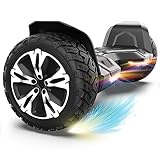
- SUPER STURDY and DURABLE – The Warrior 8.5 inch Off Road Self balancing scooter is made from a combination of UL approved materials which make up its sturdy structure that guarantees durability while keeping you safe during rides and allowing you enjoy this self balancing scooter for years to come.
- ALL-TERRAIN RIDES - With 8.5 inch solid tires and powerful motors you can be sure of a smooth and easier ride on all terrains.So, Don't hesitate to ride on grass, dirt, gravel or wet surfaces. Ride like a warrior!
- MUSIC SPEAKER INCLUDED – For the music lovers, we have added a Built-in branded music speaker to allow you play your music when riding the self balancing scooter. No ride will be more fun than this.
- SELF BALANCING BOARD – The Self balancing technology used for this scooter makes it easier and safe for new riders. Master the art of balancing in minutes.
- OUR SAFETY PROMISE – This self balancing scooter has been safety tested to UL 2272 standards and has passed strict electrical and safety testing to help ensure safe charging and riding.
Understand the PID terms
- Proportional: responds to present angle error.
- Integral: corrects persistent offset, but can wind up when the motor output is saturated.
- Derivative: adds damping, but can amplify sensor noise.
Use output limits and anti-windup. A controller that appears stable on a stand can behave differently with a rider because mass, center of gravity, friction, and motor load have changed.
Use encoders where they add value
Encoders are not strictly required for the simplest balance loop, but they can improve speed limiting, wheel synchronization, drift detection, stopping, odometry, and telemetry. They also help identify motor asymmetry. A documented older build listed encoder inputs but had not implemented them in that software version.
Keep steering subordinate to balance
Differential steering normally adds a steering command to one motor and subtracts it from the other. Limit steering at high tilt, low battery, or high speed. A steering input must not overwhelm the corrective balance command.
Independent reader supportYour contribution helps us test, update, and keep practical guides available for everyone.Common failure modes
Motors run at power-on
Floating inputs, incorrect driver modes, or a controller reset can briefly be interpreted as a drive command. One historical Sabertooth installation experienced uncontrolled startup activation and required safe input biasing. Use a hardware motor-enable line, pull-down or bias resistors, explicit neutral output before enabling, a delayed arming sequence, sensor validation, and a physical emergency stop.
The vehicle falls immediately
Check IMU orientation, axis signs, motor polarity, wheel direction, balance-zero calibration, loop timing, and whether the motor driver is actually following the intended command. Verify the correction direction with the wheels unloaded before changing PID gains.
The platform oscillates
Possible causes include excessive proportional gain, insufficient damping, noisy derivative data, structural flex, delayed sampling, motor saturation, or loose motor mounts. Reduce output limits during testing and inspect the frame before assuming the software is at fault.
The vehicle leans continuously
Look for an incorrect balance reference, accelerometer bias, gyro drift, unequal motors, unequal tire diameter, a bent axle, or a battery-voltage-dependent motor mismatch. Calibrate each side and check mechanical alignment.
The vehicle turns by itself
Inspect motor asymmetry, wheel traction, encoder scaling, steering offsets, wiring resistance, and current limits. A mechanical problem should be corrected before adding software trim.
Quick wins for a faster PC:
Scan for outdated or missing drivers - takes under a minuteDriver Scan →Repair Windows errors before they cause bigger problemsFix Now →Fix the driver behind crashes, sound loss and screen glitchesFind Drivers →The controller resets
High-current motor switching can cause voltage dips and electrical noise. Use separate regulated logic power, short protected high-current wiring, suitable grounding, suppression and layout practices, and an oscilloscope or logger where available. Keep IMU wiring away from motor-current paths.
Best Value

- Long Battery Life: SIMATE Self-Balancing scooter, a self-balancing control system, Dual 250W motors, all terrain tires, it's suitable for kids, adults, girls, boys, easy to learn and use
- Bluetooth Speakers & LED Lights: Scooter comes equipped with a built-in Bluetooth music speaker, Meanwhile, the scooter features bright LED lights and flashing light up wheels for a safer and more fun ride
- APP Control: Download our exclusive XsCar app for comprehensive control over your scooter. Power on/off, adjust lights, monitor speed and battery power, set speed modes, and more
- High Performance: 6.5" solid rubber wheels, Aluminum frame, Non-Slip Deck, top speed 7.5 mph (3 adjustable speed modes), top range 7.5 miles, max load 220 lbs. 15-degree slope
- A Love for Kids - The SIMATE self-balancing all terrain scooter makes an ideal choice for kids, adults, girls, boys, Suitable for daily activities, it's a good stuff for Birthdays and every festival
The battery voltage collapses
A battery can appear charged at rest but drop below the safe operating voltage during acceleration. Monitor voltage under load, use a conservative cutoff, fuse the pack close to its terminals, and protect all high-current conductors.
The motor driver overheats
Check stall current, repeated reversal, regenerative braking, inadequate heat dissipation, mechanical drag, and whether the controller’s continuous rating applies under the installed cooling conditions. Do not rely solely on a nominal wattage label.
Safety engineering is part of the build
Never rely on software alone for emergency stopping. Provide an independent hardware path that disables motor drive. Include a rider-presence switch, driver-enable default-off behavior, a watchdog, a fault latch where appropriate, battery fusing, guarded moving parts, enclosed terminals, strain relief, and a main disconnect.
Regenerative braking requires special attention. During deceleration or when the vehicle drives the motor, energy may flow back into the controller or battery. Verify that the motor controller, battery, and BMS can accept the current. Do not assume every controller handles regeneration safely.
A total power loss is not a controlled stop: the balancing response may disappear immediately. Design and test for predictable failure, but do not claim that a DIY vehicle remains safe after power loss unless that behavior has been specifically engineered and demonstrated.
Build from scratch, modify, or buy?
Build from scratch when:
- your main goal is control theory, robotics, fabrication, or engineering learning;
- you can construct a rigid chassis and safe motor mounts;
- you understand battery protection, high-current wiring, and embedded control;
- you can test without immediately riding; and
- you accept that the outcome may remain a prototype rather than dependable transport.
Modify an existing platform when:
- you can obtain a mechanically sound mobility base or wheelchair drivetrain;
- the motors, wheels, structure, and brakes are suitable;
- the original electronics can be isolated or replaced safely; and
- the battery system can be redesigned rather than improvised.
Buy a commercial product when:
- you need reliable transportation;
- other people will be nearby;
- you cannot independently diagnose electrical and control failures;
- the vehicle must be insured, serviceable, weather-resistant, or used in public; or
- the value is in riding rather than building.
Legal and operating considerations
Rules for DIY personal transporters vary by country, state, municipality, property owner, and insurer. Before riding anywhere beyond controlled private property, check local requirements for public-road and sidewalk use, speed, lighting, reflectors, helmets, insurance, modified vehicles, and product liability. A successful demonstration does not establish legal compliance or safety for public use.
Also remember that a video or working demonstration proves only that one machine operated under particular conditions. It does not prove structural fatigue life, braking performance, battery safety, reliability, or suitability for another rider. Many DIY projects omit complete drawings, firmware, calibration data, testing records, or a complete bill of materials; coverage of the subject has noted this documentation problem. See the discussion of DIY Segway documentation.
Free tools Windows power users keep installed
One-click scans. No signup required.
Conclusion
A home-made Segway is an excellent control-systems and fabrication challenge when approached as a staged experiment. Start with simulation and a low-energy robot, separate sensor electronics from noisy motor power, validate every motor and safety interlock with the wheels restrained, and postpone riding until the system has demonstrated predictable behavior without a person aboard.
For reliable transportation, a commercial product is usually the more responsible choice. For learning, however, a carefully limited prototype can teach inverted-pendulum dynamics, sensor fusion, PID tuning, motor control, battery engineering, and practical construction far more effectively than a parts list alone.
Quick Recap
Product prices and availability are accurate as of the date/time indicated and are subject to change. Any price and availability information displayed on Amazon at the time of purchase will apply.


Leave a Reply