Some links on this page are affiliate links: if you buy through them we may earn a commission, at no extra cost to you.
Yes—one custom controller can operate ordinary analog RGB strips, 5 V WS2812/WS2812B strips, and commonly 12 V or 24 V WS2811 strips. The project described here uses an Ai-Thinker WB2-12F module, three MOSFET channels for analog RGB, digital data for addressable strips, BLE control through a WeChat Mini Program, infrared control, and a button for changing output modes. Its claimed input range is 5–30 V, but that does not mean every strip can be connected to every input voltage.
The critical rule is to identify the strip first. Analog RGB, WS2812, and WS2811 strips use different power and control arrangements. Reversing a connector or applying 12 V to a 5 V WS2812 strip can destroy the strip or controller.
What this controller actually supports
The original project is a compact, wireless, multi-mode LED controller rather than a universal output in the literal sense. It supports three distinct electrical modes:
Recommended Free Tools
| Strip type | Typical supply | Control method | Addressing |
|---|---|---|---|
| Analog RGB | Usually 12 V; also available in 5 V or 24 V | Three PWM-switched color channels | The whole strip or cut segment changes together |
| WS2812/WS2812B | 5 V | Single-wire digital data | Usually one logical pixel per LED or pixel package |
| WS2811 strip | Commonly 12 V or 24 V | Single-wire digital data | Often one logical pixel per group of three physical LEDs |
The project overview specifies the WB2-12F module, a claimed 5–30 V input, a 3.3 V step-down supply for the module, a 5 V WS2812 output, 12/24 V WS2811 compatibility, BLE control, NEC infrared reception, button-based mode selection, an LCSC EDA PCB, and a Fusion 360 snap-fit enclosure. See the original project overview for the author’s design and build notes.
#1 Best Overall
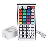
- Multi-Functions-- There are 20 colors and 5 light pattern: Static/Flash/Strobe/Fade-change/RGB Smooth-change. Easy for you to turn ON/OFF strip lights, DIY colors as you like and adjust brightness
- Compatible with RGB Strip-- Work with SMD 5050 3528 2835 RGB led light strips with 4-Pin connectors. Not for RGBW strips which has 5-pin connectors. This product will not work while the led strip is not 4-pin, nor it uses other than 12V or more than 6A.
- Safe to Use---Input DC 12V, Max output current is 6A. The remote controller has been approved CE, RoHs, Fcc certification, Low voltage, Low heat, no radiation, it is safe and touchable
- IR Remote --- IR remotes have a performance range of about 30 feet. Please note: IR remotes must be pointed directly at the devices you are trying to control
- Easy to Use --- If you want a straight-forward, simple to use, cost-effective remote, our this 44 keys IR remote controller dimmer is the way to go
Identify the strip before wiring it
Do not rely only on a seller’s use of the word “RGB.” That label may describe either an analog strip or an addressable strip.
- Analog RGB: commonly has four conductors: a common positive connection plus red, green, and blue returns. It has no data-in arrow or individually controlled pixels.
- WS2812/WS2812B: commonly has 5 V, ground, and data connections. Look for
DIN,DOUT, or directional arrows. - WS2811: may use four-pin connectors or vendor-specific wiring. Confirm whether the strip is rated for 12 V or 24 V and whether its controller IC addresses groups of three LEDs.
Also check whether the strip is common-positive or common-negative, locate the input end marked DIN, and count logical pixels rather than assuming that every physical LED is independently controlled. RGBW, RGB+CCT, SK6812 RGBW, APA102, and other formats are not automatically supported by a three-channel analog RGB and one-wire addressable design.
How the three modes work
1. Analog RGB mode
In analog mode, the strip receives a continuous supply voltage and the controller switches the red, green, and blue returns with three MOSFET channels:
Quick wins for a faster PC:
Repair Windows errors before they cause bigger problemsFix Now →Fix the driver behind crashes, sound loss and screen glitchesFind Drivers →DC supply + ───────── common positive of RGB strip
└──────── controller supply
RGB red ───── MOSFET channel 1 ─── ground
RGB green ─── MOSFET channel 2 ─── ground
RGB blue ──── MOSFET channel 3 ─── ground
MCU PWM outputs ───────── MOSFET gatesThe MOSFETs must be logic-level devices that turn on properly from the module’s GPIO voltage. The design also needs appropriate gate resistors, gate pulldowns, current-rated traces and connectors, and enough copper to dissipate heat. A MOSFET suitable for a small test strip may overheat on a long, high-current strip.
Parts such as IRLZ44N and STP55NF06L are examples mentioned in WLED’s analog LED guidance, not mandatory parts for this particular WB2-12F design. Choose devices only after calculating the strip current and checking the actual schematic and thermal layout.
Rank #2

- 【44 Keys Remote Controller】You can choose 20 static colors, adjust brightness, turn On/Off, control modes: Flash, Strobe, Fade, RGB Smooth-change, Static, DIY frequently-used modes as you like.
- 【2-IN-1 Connectors】Work with DC 12V-24V power supply, the other 4-pin ends for 2 reel LED RGB strip lights. One remote can control 2 reels of strips at the same time.
- 【IR Remote】The IR remote has about 30 feet effetive control distance. Please note: IR remote must be pointed directly at the devices you are trying to control.
- 【Easy to Use】If you want a straight-forward, simple to use, cost-effective remote, our this 2-IN-1 remote is the way to go.
- 【For RGB Strip Light】Special for 5050 3528 4-pin LED strip light, work with 12V power supply (Package will Not come with power or strip)
2. WS2812 mode
WS2812 strips use a 5 V power rail and a timed, one-wire data signal:
5 V supply ───────────── WS2812 +5 V
Ground ───────┬───────── WS2812 GND
              └───────── controller ground

MCU data ── level shifter ── series resistor ── WS2812 DIN
Never connect a WS2812 strip directly to 12 V or 24 V. The controller’s claimed 5–30 V input range describes the board’s input architecture, not the safe supply voltage for every output strip.
3. WS2811 mode
WS2811 strips commonly use a higher-voltage LED supply while retaining a digital data connection:
12/24 V supply ───────── WS2811 strip power
Ground ───────┬───────── WS2811 ground
              └───────── controller ground

MCU data ── signal conditioning ── WS2811 DIN
Match the supply to the marking on the actual strip. A 12 V strip is not automatically suitable for 24 V, and a 5 V supply will not correctly power a 12 V or 24 V strip. Many WS2811 strips use three physical LEDs per logical pixel, so an effect configured for 100 pixels may control 300 physical LEDs in groups.
Power architecture and protection
Keep these three questions separate:
- What voltage can enter the controller board? The project description claims 5–30 V.
- What voltage does the strip require? This is determined by the strip label and datasheet.
- What logic voltage does the data input recognize? This depends on the LED IC, supply voltage, wiring, temperature, and tolerances.
The WB2-12F requires a regulated 3.3 V rail. The project also describes a 5 V WS2812 path and a 12/24 V WS2811 path. Confirm the actual PCB schematic before assuming that every output is regulated, protected, or suitable for continuous maximum-current operation.
Rank #3

- Single Color LED Strip Lights RF Remote Control - Works with 5050 3528 5630 3014 Single Color LED Strip Lights. Remote turn on/off, dim the brightness and change dynamic flashing mode and speed.
- LED Light Dimmer Switch - The LED Remote Controller supports 10 levels brightness adajustment, also with 25% 50% 100% quick brightness change buttons. 8 dynamic modes and 10 levels dynamic speed adjustment. It also built- in automatic shutdown memory function.
- Wide Application - Simple add this LED controller to remote control your LED lamps, point-source light, flexible strip light, wall washer light, glass curtain wall light and so on, pecfect for DJs, Musicians, Parties and More.
- Working Voltage - DC 12V-24V. Max Current: 12A. 11 key RF Remote control with 433MHz Frequency. Remote distance: 15m at open area. Please note power adapter is not included.
- Single Control & Multi Control - One remote is able to control multi receivers by default. If you want separate control, restart the power of the receiver, and within 5 seconds, press and hold "SPEED-" and "SPEED+" buttons at the same time for about 10 seconds until lights flash, now the frequency will be changed and only this remote can control this receiver.
For larger installations, size the supply and wiring for the strip’s real current. Use an input fuse, appropriately rated connectors, short high-current paths, and power injection where voltage drop becomes significant. WLED’s wiring guidance recommends considering injection above about 150 LEDs, but that is practical guidance rather than a universal engineering threshold. It also warns against connecting the positive rails of two supplies to the same strip.
Power the strip and controller in parallel where appropriate, with a shared ground. A voltage regulator changes a power rail; it does not convert a 3.3 V data signal into a robust 5 V logic signal.
Use proper data-level shifting
The WB2-12F is a 3.3 V module, while many 5 V addressable LED inputs expect a higher logic-high voltage. Some strips work with a direct 3.3 V signal, but that can be marginal and may fail with a different strip, longer cable, lower supply voltage, or different temperature.
For dependable operation, use a fast 3.3-to-5 V logic translator such as an appropriate AHCT-family device or a purpose-built addressable-LED shifter. WLED specifically recommends suitable high-speed level shifting and warns that generic slow bidirectional I²C level shifters are not appropriate for fast LED data. Adafruit explains the threshold variations in its logic-level guide.
Keep the data wire short, route data with its ground reference, place a small series resistor near the data output if the design supports one, and connect the grounds of the controller, strip, and strip power supply.
Do these 3 things before closing this tab:
1Repair Windows errors before they cause bigger problems2Scan for outdated or missing drivers - takes under a minute3Clear out junk files and repair common Windows errorsRank #4

- This is a new Multi-color RGB LED controller with powerful functions and small size, which can present many special dynamic modes and bring new applications for multi-color LED decoration.
- This Mini RGB dimmer is used to control a variety of single-color fixtures with LEDs as the light source, and can realize 19 dynamic effects and 20 static effects; adjustable dynamic speed and brightness and other features.
- This Led strip light switch can easily change the dynamic mode, speed and brightness by pressing three keys on its slim body. It also has an automatic memory function. It is the perfect companion for your LED lights.
- This 3 Keys RGB Led brightness controller cable has 3 buttons. MODE key: dynamic mode key, press the mode key to cycle through 19 dynamic effects; COLOR key: static color key, press the COLOR key to switch among 20 static colors; SPEED/BRIGHT key: adjust the speed in MODE mode, adjust the brightness in COLOR mode, and the long button will shut down the power for 1 second, stable performance, good operation, simple wiring Convenient.
- Widely used in halls, buildings, indoor, outdoor and other places.
WB2-12F controls and firmware
The project uses the WB2-12F because it combines a small wireless module with enough control capability for PWM, addressable data, input handling, and wireless control. Its reported user interface includes:
- A button that cycles through standard RGB, WS2812, and WS2811 modes.
- A possible long-press action for BLE control.
- NEC infrared-code reception.
- BLE control through a WeChat Mini Program.
- Automatic discovery of the preset Bluetooth name by the application.
A sensible firmware state machine is:
Power on
  └─ load saved mode
       └─ initialize matching output
            └─ accept button, IR, and BLE commands
                 └─ update PWM or digital LED frame
A reproducible firmware build should document the GPIO map, PWM settings, addressable-data implementation, pixel count, color order, BLE service and characteristic format, button debounce time, long-press duration, IR command map, startup-safe state, and mode persistence. The public project description does not visibly provide all of those details, so do not assume that the design can be rebuilt from the overview alone.
Color order is another common trap. WS2812B strips often use GRB and WS2811 strips often use RGB, but neither is universal. WLED’s FAQ recommends configuring the actual strip rather than relying on its family name.
Independent reader supportYour contribution helps us test, update, and keep practical guides available for everyone.PCB and enclosure considerations
The author reports designing the PCB in LCSC EDA, passing design-rule checking, and exporting it for JLCPCB fabrication. The WB2-12F was described as difficult to hand-solder, with a hotplate used before the remaining components were soldered manually. The enclosure was designed in Fusion 360 as a screwless snap-fit case.
What’s actually slowing this PC down?
Pick the symptom - the matching free tool is one click away.
For a robust revision, separate high-current LED paths from sensitive MCU and data traces. Provide adequate copper around MOSFETs and regulators, place decoupling capacitors close to the relevant devices, label every connector, and add test points for input voltage, 5 V, 3.3 V, ground, and digital data.
Best Value
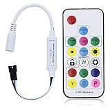
- Input voltage:DC5V/DC12V/DC24V; Input current:5A max, please don't use for project that draws more than 5A current.
- SP103E controller supports 5V WS2812B and 12V/24V WS2811LED lights.It can’t control SK6812 RGBW LED lights and regular RGB LED without driver IC.
- Contain 200 kinds of color modes, such as rainbow, wave, breathing, strobing, gradual change, color cycle, comet, static, fading, chasing, which are vivid and beautiful. Color changing speed and brightness are adjustable.
- 15m long distance wireless RF remote control; mini size; convenient to use. DC 5V~24V input; But it can’t regulate the output voltage.Please choose power supply according to your led lights, not the controller.
- Support setting controlled pixels number. Control up to 2048 pixels at most. R/G/B keys can be reordered to match with your LED light if needed.
Useful design improvements include reverse-polarity protection, an input fuse, keyed connectors, programming or bootloader pads, and a clear isolation strategy so unused output paths cannot be energized accidentally. Plug-in connectors may simplify assembly but increase enclosure thickness. The project page also warns that its connectors are not foolproof, so label voltage, ground, data, and direction on the PCB and housing.
Safe assembly and first power-up
- Inspect solder joints, especially the WB2-12F, regulator, MOSFETs, and connectors.
- Check resistance between input positive and ground, 5 V and ground, and 3.3 V and ground.
- Inspect the board for solder bridges and reversed components.
- Use a current-limited bench supply for the first power-up.
- Verify the 3.3 V rail before connecting an LED strip.
- Verify the 5 V rail in WS2812 mode and the selected WS2811 output voltage.
- Test the button, wireless connection, and IR input with no strip attached.
- Connect a short, low-current test strip of the correct type and voltage.
- Begin at low brightness and increase it gradually while checking MOSFET, connector, regulator, and wiring temperature.
Do not hot-switch between incompatible strip types unless the hardware explicitly guarantees that unused outputs are isolated. The safest procedure is to remove power, select the correct mode, verify the connector orientation and voltage, then reconnect power.
Troubleshooting
| Symptom | Likely causes |
|---|---|
| Nothing lights | Wrong mode, wrong polarity, no shared ground, incorrect data direction, missing supply, or an incorrect strip voltage. |
| Wrong colors | Incorrect RGB/GRB order, wrong strip configuration, or an analog common-positive/common-negative mismatch. |
| Random flicker | Marginal 3.3 V logic, long data wiring, poor ground, electrical noise, or supply instability. |
| Only the first pixel responds | Reversed data direction, damaged first pixel, incorrect data level, or a broken connection after the first pixel. |
| The far end is dim or discolored | Voltage drop, undersized wire, insufficient power injection, or an overloaded supply. |
| An analog strip stays on | Incorrect common connection, a MOSFET gate that is not pulled low during reset, or an unsuitable MOSFET drive arrangement. |
| The controller resets | Supply sag, buck-converter overload, inadequate grounding, or noise from the LED load. |
| WS2811 effects look coarse | The strip uses grouped three-LED segments, so the logical pixel count is lower than the physical LED count. |
| MOSFETs become hot | Excessive strip current, insufficient gate drive, high MOSFET resistance, inadequate copper, or inadequate cooling. |
Build this controller or use WLED?
Build the WB2-12F design if you specifically want a compact custom PCB, BLE or WeChat control, infrared input, custom connectors, and the experience of designing the electronics and firmware yourself. It is also a useful learning project because it forces you to handle three different power and signaling systems.
Choose an ESP32 running WLED when Wi-Fi control, a web interface, OTA updates, integrations, broad community documentation, and easier expansion matter more than reproducing this exact BLE design. WLED currently recommends ESP32 for new installations. A commercial WLED controller is the safer choice for high-current, long-run, vehicle, building, or public-facing installations where verified protection and support matter more than experimentation.
For a custom WLED build, select the controller, level shifter, power supply, fuse, strip voltage, connector, and wire as a matched system. A basic analog RGB controller cannot drive WS2811 or WS2812 data, and a 5 V-only controller does not automatically power a 12 V or 24 V strip.
What remains to be verified before copying the PCB
The project overview is strong as a concept description but does not visibly establish every detail needed for a production-ready reproduction. Confirm these items from the downloadable design files or the author before ordering boards:
- Complete schematic and bill of materials.
- Exact buck-converter and MOSFET part numbers.
- Maximum current per analog channel and total board current.
- Fuse values and reverse-polarity protection.
- Connector pinout and live mode-switching behavior.
- Logic-level-shifter implementation.
- Exact GPIO assignments and firmware source or build procedure.
- BLE packet format and WeChat platform requirements.
- Maximum addressable pixel count and supported color orders.
- Thermal performance under maximum load.
- Availability of the enclosure’s editable or printable files.
That distinction matters: “5–30 V input,” “universal,” and “plug-and-play” describe the project’s intended capability, not a guarantee that every strip, current level, connector, and installation condition is safe.
Crashes, No Sound, or Screen Glitches?
Random freezes, missing sound and display glitches usually trace back to one bad driver. Find and replace yours safely.Free scan · under a minutePC Slower Than It Used to Be?
A free scan shows the junk files, broken settings and background clutter dragging Windows down - then fixes them in one click.Free scan · Windows 10 & 11Quick Recap
Product prices and availability are accurate as of the date/time indicated and are subject to change. Any price and availability information displayed on Amazon at the time of purchase will apply.


Leave a Reply