Some links on this page are affiliate links: if you buy through them we may earn a commission, at no extra cost to you.
You can build an Arduino gadget that responds to changes in skin conductance. You cannot use it to reliably tell whether someone is lying. This project is best treated as a DIY stress-response meter: a hands-on way to explore sensors, signal noise and physiology, not a truth test.
What this “truth meter” measures
The device measures skin conductance, often called galvanic skin response (GSR) or electrodermal activity (EDA). Sweat-gland activity changes how readily the skin conducts electricity. The fingers and palms are commonly used because they contain many eccrine sweat glands.
A change in the sensor reading means the measured electrical signal changed. It may accompany nervousness, surprise, embarrassment, anger, excitement or physical activity; it can also result from heat, perspiration, movement or changing electrode contact. The sensor cannot identify which cause produced a change, and it cannot label an answer true or false.
Quick wins for a faster PC:
Fix the driver behind crashes, sound loss and screen glitchesFind Drivers →Clear out junk files and repair common Windows errorsFree Scan →Scan for outdated or missing drivers - takes under a minuteDriver Scan →The American Psychological Association’s overview of polygraphs describes important scientific limitations, including the possibility that truthful people react because they are nervous. A single-channel Arduino circuit is much simpler than a professional polygraph, which can record several physiological signals and uses structured questioning and examiner interpretation. Adding pulse or breathing sensors makes a demonstration richer; it does not make the truth inference reliable. The American Polygraph Association’s FAQ describes aspects of professional examinations, but professional practice does not validate this hobby circuit.
#1 Best Overall

- QUALITY ANALOG EDA/GSR DESIGN - Purpose-built maker-grade board uses a low-voltage electrode bias and TIA-based analog front end to provide a stable, responsive analog signal for electrodermal activity and galvanic skin response experiments.
- RESPONSIVE ACROSS PRACTICAL SKIN CONDITIONS - The analog front end is designed to maintain useful signal response across changing skin conductance, with bench characterization over an approximately 50 kOhm to 1.5 MOhm practical resistance range.
- HIGH-QUALITY Ag/AgCl CONTACTS - Reusable finger straps use Ag/AgCl skin-contact surfaces, secure hook-and-loop construction, and less than 0.1 ohm stud-to-contact resistance to support consistent, low-resistance signal capture.
- SIMPLE ANALOG INTEGRATION - Operates from a recommended 3 to 5 V supply and provides straightforward VIN, GND, and VOUT connections for easy connection to microcontroller ADCs and custom electronics.
- BUILT FOR SERIOUS MAKER AND PROTOTYPING WORK - Robust reusable contacts, a dedicated analog sensing architecture, and convenient standard interfaces make the kit well suited for biofeedback, HCI, psychophysiology, affective computing, biometrics, wearable sensing, data logging, and embedded development.
Parts and safety
- An Arduino UNO R4 Minima or another compatible Arduino board you already have.
- A documented GSR sensor module with two electrodes. Follow that module’s pinout and operating-voltage instructions; “GSR” products do not all share the same wiring or output range. See the Seeed Grove GSR documentation for that module.
- Three LEDs, three 220–330 Ω current-limiting resistors, a breadboard and jumper wires.
- A USB cable or suitable battery power source, plus a computer for viewing serial readings.
Safety: Use only a battery-powered or USB-powered low-voltage hobby circuit. Never connect a person to mains electricity, an outlet or an unknown wall-adapter output. Do not use the device on broken, irritated or wet skin, or on someone with an implanted electronic medical device unless a qualified clinician says it is appropriate. Stop immediately if the participant feels pain, tingling, burning or discomfort. Get informed permission; do not use readings to accuse, punish, interrogate or make school, employment, relationship or legal decisions. This is not medical equipment.
Use a ready-made, documented GSR module rather than copying an old foil-electrode circuit without checking its current limiting, power source and sensor documentation. Arduino’s older basic project is a historical example, not a substitute for checking the circuit you build.
Wire the sensor and indicator LEDs
With the Arduino disconnected from the participant, connect a module whose documentation specifies 5 V operation as follows. If its documentation specifies another voltage or different pin labels, follow that documentation instead.
The Tool Desk
Outbyte Driver Updater FREEScan for outdated or missing drivers - takes under a minuteDriver Scan →Outbyte PC Repair FREEClear out junk files and repair common Windows errorsFree Scan →Rank #2
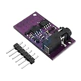
- -6701 GSR Skin Sensor Module Sensor Module Analog Measuring EDA GSR for Arduino Diy Kit Electronic PCB Board Module
| Part or pin | Connection |
|---|---|
| GSR VCC | Arduino 5V, only if the module supports 5 V |
| GSR GND | Arduino GND |
| GSR SIG/OUT | A0 |
| Green LED | D8; connect the other LED leg through its resistor to GND |
| Yellow LED | D9; connect the other LED leg through its resistor to GND |
| Red LED | D10; connect the other LED leg through its resistor to GND |
Use one resistor in series with each LED. The colors are only display conventions: green means a relatively small deviation from the chosen baseline, yellow a moderate deviation and red a larger one. They must not be labeled as truth or deception indicators.
Upload the Arduino sketch
In the Arduino IDE, select the connected board and port, paste the sketch below, then upload it. It uses standard Arduino functions such as analogRead() and digitalWrite(), rather than a board-specific sensor library. Open the Serial Monitor at 115200 baud.
const int GSR_PIN = A0;
const int GREEN_LED  = 8;
const int YELLOW_LED = 9;
const int RED_LED    = 10;

const int BASELINE_SAMPLES = 100;
const int RUNNING_SAMPLES = 10;

// Illustrative display thresholds; tune for your module and setup.
const int YELLOW_THRESHOLD = 25;
const int RED_THRESHOLD = 75;

long baselineTotal = 0;
int baseline = 0;

int readAverage(int count) {
  long total = 0;
  for (int i = 0; i < count; i++) {
    total += analogRead(GSR_PIN);
    delay(10);
  }
  return total / count;
}

void showLevel(int deviation) {
  digitalWrite(GREEN_LED, LOW);
  digitalWrite(YELLOW_LED, LOW);
  digitalWrite(RED_LED, LOW);

  if (deviation >= RED_THRESHOLD) {
    digitalWrite(RED_LED, HIGH);
  } else if (deviation >= YELLOW_THRESHOLD) {
    digitalWrite(YELLOW_LED, HIGH);
  } else {
    digitalWrite(GREEN_LED, HIGH);
  }
}

void setup() {
  pinMode(GREEN_LED, OUTPUT);
  pinMode(YELLOW_LED, OUTPUT);
  pinMode(RED_LED, OUTPUT);

  Serial.begin(115200);
  delay(1000);
  Serial.println("Keep fingers still. Establishing baseline...");

  for (int i = 0; i < BASELINE_SAMPLES; i++) {
    baselineTotal += analogRead(GSR_PIN);
    delay(20);
  }
  baseline = baselineTotal / BASELINE_SAMPLES;

  Serial.print("Baseline: ");
  Serial.println(baseline);
  Serial.println("time_ms,raw,filtered,deviation");
}

void loop() {
  int raw = analogRead(GSR_PIN);
  int filtered = readAverage(RUNNING_SAMPLES);
  int deviation = abs(filtered - baseline);

  showLevel(deviation);

  Serial.print(millis());
  Serial.print(",");
  Serial.print(raw);
  Serial.print(",");
  Serial.print(filtered);
  Serial.print(",");
  Serial.println(deviation);

  delay(100);
}
During setup, the sketch averages 100 readings to establish a baseline. In the loop, it averages 10 readings for a less jumpy display, calculates the absolute difference from that baseline and prints elapsed milliseconds, a raw reading, the averaged reading and the difference. The raw and filtered values are analog-to-digital converter counts, not a universal measurement of stress.
Rank #3

- Build a 37-Module Sensor Lab: Add motion, distance, light, sound, temperature, touch, display and control functions to compatible UNO, MEGA, Nano, ESP-32 or STM32 projects for prototyping, classroom experiments and maker builds
- Explore Input Sensors and Motion: Experiment with GY-521 motion sensing, PIR detection, ultrasonic ranging, temperature and humidity, DS18B20, flame, Hall, touch, light, sound, tilt, tracking and obstacle-avoidance modules
- Add Displays, Timing and Control: Use the LCD1602, DS1307 real-time clock, joystick, rotary encoder, relay, buzzers, RGB LEDs and infrared modules to build clocks, alarms, counters, status displays and automated projects
- Follow Guided Projects Materials: Use digital tutorial materials, datasheets, wiring diagrams and example code for compatible UNO R3, MEGA 2560 and Nano boards, then adjust thresholds, timing and logic to create custom experiments
- Module-Only Expansion Kit: Controller board, USB cable, breadboard and jumper wires are not included; use 6.5–9 V DC only with the included power module, verify pin requirements before wiring and keep the laser emitter away from eyes
The yellow and red thresholds of 25 and 75 are illustrative settings, not scientific cutoffs. Sensor output can vary with module design, skin moisture, electrode pressure, wiring, board and sampling. Watch the serial readings first and adjust the thresholds to make the LEDs respond to changes in your setup. A red LED means only that the signal moved farther from the selected baseline than the chosen threshold.
Calibrate and run a respectful demonstration
- Explain the project and ask the participant’s permission before they handle or wear the electrodes.
- Have them sit comfortably. Ensure the contact surfaces and skin are clean and dry.
- Place the electrodes consistently on two fingers, using light, repeatable pressure. Keep the participant’s hand still.
- Allow a quiet baseline period of 30–60 seconds. The sketch’s initial baseline is shorter; for a more informative demonstration, observe the readings longer and note any drift.
- Ask harmless, neutral questions with known truthful answers, then harmless questions likely to prompt interest or surprise. Record each question’s time alongside the serial log.
- Repeat questions in a different order and compare the signal with the question timing. Treat movement, changing pressure and room conditions as possible artifacts.
A useful classroom question is “How does skin conductance change during rest, mental arithmetic, surprise and questioning?” Compare those conditions rather than asking whether the device caught a lie. Keep electrode placement and movement as consistent as possible, and compare a participant mainly with their own readings. A baseline from one person is not a universal truth scale.
What the readings can—and cannot—show
| Observation | What it supports | What it does not prove |
|---|---|---|
| A large GSR change | The measured skin-conductance signal changed | That the person lied |
| No large change | No large change was recorded by this setup | That the person told the truth |
| Repeated changes during arithmetic | The signal changed during a mentally demanding task | Deception |
| A change when fingers move | Movement or contact may have affected the measurement | An emotional response or a lie |
| Different people have different readings | Readings vary between participants and setups | That one person is more truthful |
A truthful person may react strongly because they feel judged, are surprised, or are uncomfortable. A deceptive person may show little change. The circuit cannot distinguish among those explanations. The APA’s overview summarizes broader concerns about treating polygraph responses as proof; the limitations are even more fundamental in a one-sensor hobby demonstration.
Rank #4

- ❃❃ High quality sensor module kit for Arduino and Raspberry pi.
- ❃❃ Those sensors will often being used in the beginner's project. It is included sound and obstacle avoidance sensor, obstacle avoidance sensor, temperature and humidity sensor, ultrasonic, a path tracing module and infrared human body induction sensor.
- ❃❃ For the beginner, 22 in 1 Modules Sensor Learning Package includes most projects design for those beginners and who want to know more about Arduino, UNO R3 Nano V3.0 Mega 2560 Mega 328 Project Raspberry Pi and STM32.
- ❃❃ We eliminate many old-fashioned sensors which have low reliability and duplicate function as other sensor in the kit, the UMLIFE modules sensor kits are choosed carefully for our user.
- ❃❃ With this kit, we will take you from knowing to utilizing, you are able to do more experiment, get your more idea into real action without the restriction of hardware and software. ❃❃ Any questions, you can contact us and we will give you a satisfied solution.
Troubleshoot common problems
The reading never changes
- Check the module’s VCC, GND and signal wiring against its documentation, and confirm the signal wire goes to the pin named in the sketch, A0.
- Print raw
analogRead()values and confirm the Serial Monitor is set to 115200 baud. - Check that the electrodes make consistent contact and that the module is powered at its specified voltage.
- Disconnect the participant before trying a known-good analog input or testing wiring.
The reading stays near zero or maximum
Possible causes include incorrect wiring, a short, missing common ground, a damaged module or a signal-voltage mismatch. Disconnect the person before troubleshooting. Do not keep changing circuit connections while someone is touching the electrodes.
The output is noisy or drifts
Shorten and secure wires, steady the breadboard, keep sensor leads away from USB and LED wiring, and use consistent electrode placement and pressure. Averaging can reduce rapid noise, but it cannot correct movement artifacts. Gradual drift can come from warming fingers, perspiration, changing grip, adaptation or room temperature; it does not by itself indicate a response to a question.
The LED changes when the participant moves
Movement can change electrode pressure and the electrical path. Treat that as a possible measurement artifact, not evidence of emotion or deception.
Best Value
![Arduino Sensor Kit - Base [TPX00031] - Essential Sensors for Beginners, Includes 10+ Sensors for DIY Projects & Learning](https://m.media-amazon.com/images/I/41VrImqpp2L._SL160_.jpg)
- Comprehensive Sensor Collection: The Arduino Sensor Kit - Base [TPX00031] includes over 10 essential sensors, such as temperature, light, motion, and humidity sensors, providing a complete foundation for learning and experimentation in electronics and IoT applications.
- Ideal for Beginners and Education: This kit is designed for beginners, making it perfect for educators, students, and hobbyists who want to dive into sensor-based projects. With easy-to-follow instructions, you can start building interactive systems and gain hands-on experience in electronics.
- Versatile and Expandable: The included sensors cover a wide range of applications, from environmental monitoring (temperature, humidity, air quality) to motion detection and light sensing. This makes the kit highly versatile, allowing for endless customization and experimentation in various fields such as home automation, robotics, and IoT.
- Complete Learning Platform: Along with the sensors, the kit includes access to a variety of resources, including tutorials and example projects, to help you get started quickly. You'll learn how to wire, program, and use each sensor to create interactive and responsive systems.
- Perfect for DIY Projects: Whether you're building a weather station, a smart home system, or a motion-activated alarm, this kit gives you the essential sensors to create functional, sensor-driven projects. The Arduino Sensor Kit - Base is the perfect tool for hands-on experimentation, prototyping, and learning.
An Uno R4 tutorial or library behaves differently
This sketch uses basic Arduino APIs and avoids relying on an AVR-specific library. The UNO R4 WiFi keeps the Uno form factor and 5 V operation, but the R4 family is not internally identical to the classic AVR-based Uno. Older libraries may need porting or replacement.
Optional upgrades
- Graph or save the serial output on a computer to see drift, changes and recovery over time; Arduino’s USB Polygraph project is an example of a broader multi-sensor and visualization demonstration, not a professional truth test.
- Add a pushbutton to mark when a question is asked, or add a pulse or respiration sensor to compare physiological channels.
- Build an enclosure or try a wireless dashboard if you want to explore packaging or remote logging.
These additions can make the project a more useful physiology logger. They do not turn arousal signals into a reliable measure of truthfulness.
Quick Recap
Product prices and availability are accurate as of the date/time indicated and are subject to change. Any price and availability information displayed on Amazon at the time of purchase will apply.


Leave a Reply