Windows Errors? Fix Them Before They Spread
Repair common Windows errors and clear accumulated junk for a smoother, more stable PC - no reinstall needed.Free scan · no reinstallOutdated Drivers Are Slowing You Down
One free scan finds every outdated or missing driver and matches the right update for your exact hardware.Free scan · exact hardware matchSome links on this page are affiliate links: if you buy through them we may earn a commission, at no extra cost to you.
Automatic street-light control and fault detection work best as one resilient system: a local controller uses schedules, ambient light, and—where appropriate—motion or radar sensing to control each luminaire, while current, power, driver, optical, and communications data reveal failures. A simple LDR-and-relay circuit can demonstrate the principle, but roadway deployment requires outdoor-rated electrical hardware, surge protection, defined lighting levels, offline operation, cybersecurity, and a maintenance workflow.
For most municipal, campus, industrial-park, and infrastructure projects, the safest pattern is scheduled or astronomical operation with a minimum background level, adaptive brightening when road users are detected, and local fallback when communications fail. Turning lights completely off whenever no motion is detected is not a universally safe design.
What automatic street-light control includes
Automatic control ranges from a standalone photocell to an individually addressable, networked lighting system. The category is not one standardized product or method. A complete installation normally contains five layers:
The Tool Desk
Outbyte PC Repair FREEClear out junk files and repair common Windows errorsFree Scan →Outbyte Driver Updater FREEScan for outdated or missing drivers - takes under a minuteDriver Scan →- Lighting hardware: LED luminaires, drivers, poles, power circuits, fuses or breakers, surge protection, and optional photocell or control receptacles.
- Sensing: ambient-light, motion, radar, traffic, current, power, voltage, temperature, door, tilt, and tamper sensors.
- Local control: an outdoor lighting controller, microcontroller or industrial controller, relay or contactor, dimming interface, and fail-safe fallback.
- Communications: wired power-line communication, cellular, NB-IoT, LoRaWAN, RF mesh, Wi-Fi, or another suitable network.
- Central management: schedules, dimming profiles, asset records, maps, alarms, energy reports, firmware management, and maintenance workflows.
The design objective is not simply to switch a lamp. It is to provide the required light at the required time, detect abnormal conditions, preserve safe operation during outages, and help maintenance teams repair the correct asset quickly.
#1 Best Overall

- ✦ UL LISTED ✦ Meets standards for use with commercial and residential light fixtures
- ✦ NEXT GEN ELECTRONICS ✦ Latest generation electronic trigger circuit offers superior performance and reliability than old photocell with squiggly red wires
- ✦ STANDARD FIT ✦ Standard shape and size for use with residential outlet box (0.6-inch opening), post lamp poles or wall packs. Built-in time delay prevents load temporarily switching off due to drive-by vehicle headlights, lightening or light flash
- ✦ WEATHERPROOF ✦ This photocell control has an IP65 protection rating for outdoor applications. Water resist body protects the sensor against weather elements such as rain and dust. Optional frosty cap adds aesthetics to the photocell (product unit is IP65 rated without frosty cap)
- ✦ ELECTRICAL SPECS ✦ 120V-277V 60Hz, 600W Tungsten; incandescent, fluorescent, LED, halogen, mercury vapor, high pressure sodium, and CFL compatible for outdoor lamp post light, wall packs, flood lights and wall scones
Control methods, from basic to networked
Photocell or LDR control
A light-dependent resistor (LDR), photodiode, or commercial photocell switches lighting when measured ambient illuminance crosses a threshold. It is inexpensive, autonomous, and suitable for small isolated installations or low-voltage demonstrations.
Its weaknesses are important in construction and public-realm projects. Dirt, insects, snow, water, nearby artificial light, tree shadows, poor orientation, and threshold chatter can cause early switching, delayed switching, or repeated cycling. A photocell also cannot reliably distinguish a healthy luminaire from a luminaire that has received an “ON” command but produces little or no useful light.
Time-clock and astronomical control
A real-time clock, astronomical calendar, or central schedule can operate lights according to the site location and date. This is more predictable than relying on a local sensor alone, but the controller must retain accurate time, location, and—where relevant—daylight-saving settings. Battery backup or non-volatile timekeeping is valuable during power interruptions.
Recommended Free Tools
Fixed schedules and scheduled dimming
A scheduled system can use different output levels throughout the night. For example, a road may operate at a high level during the evening peak, reduce output during low-traffic hours, and increase output again before morning. The selected levels must remain consistent with the approved lighting design, road classification, pedestrian activity, glare limits, weather conditions, and applicable local requirements.
Adaptive lighting with motion or radar
PIR sensors, radar, video, vehicle detectors, and other presence sensors can raise light output when a person or vehicle approaches. The current zone and, where appropriate, adjacent poles can brighten ahead of the road user before returning gradually to a background level.
PIR can suit paths, campuses, and relatively controlled environments, but its range and detection can be affected by occlusion, speed, and temperature. Radar generally offers a broader roadway detection capability and works in darkness, but costs more and requires careful configuration to limit cross-traffic, foliage, rain, and other false triggers.
Adaptive lighting should normally retain a minimum background level rather than creating isolated dark gaps. Zone coordination, fade timing, detection range, and hold time are safety and comfort parameters—not merely software preferences.
Rank #2
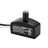
- Automatic Dusk to Dawn Control – Built-in photocell sensor automatically turns lights ON at dusk and OFF at dawn, ensuring hands-free operation and energy savings
- Durable & Safe – ETL Listed lighting control standard and FCC PART 15, Class B compliant; rated for 50,000 hours lifespan with a 5-year warranty for reliable performance
- Electrical Rating – Input: 120V AC, 50/60Hz; Maximum Load: 100W incandescent, 55W fluorescent, 55W LED driver; Ultra-low 0.5W power consumption
- Easy Installation – Mounts in a 3/8-inch hole (M9x1.0 pipe thread) and hard-wires directly to your fixture. Wiring: Black = Line, White = Neutral, Red = Load
- Wide Application – Designed for installation inside weatherproof outdoor fixtures, including wall packs, driveway and walkway lights, post lamps, pole lanterns, and entryway porch lights
Networked individual control
With networked lighting, each pole or luminaire has an addressable controller. Operators can change schedules, inspect status, locate assets, receive alarms, and review energy data remotely. Platforms such as Schréder EXEDRA describe remote scheduling, fault detection, energy and CO2 reporting, multi-site management, and third-party integration.
Networked control adds recurring connectivity, software, cybersecurity, commissioning, and maintenance responsibilities. It should not eliminate local operation: a pole should continue using its stored schedule if the cellular network, gateway, or cloud service becomes unavailable.
What counts as a street-light fault?
A useful system separates commanded-state faults from electrical, physical, sensor, and communications faults. “Failed” is too vague to guide a repair crew.
| Fault group | Examples | Likely evidence |
|---|---|---|
| Luminaire | No light when commanded on, degraded output, flicker, intermittent operation, wrong dimming level, abnormal optical or colour performance | Current, power, optical confirmation, driver diagnostics, inspection |
| Driver and power | Driver failure, overtemperature shutdown, voltage loss, overcurrent, abnormal power factor, surge damage, fuse or breaker trip | Voltage, current, real power, temperature, driver data, panel status |
| Wiring and pole | Open circuit, short circuit, loose connection, water ingress, cable theft, grounding or insulation problem, pole-door opening | Electrical tests, tamper switch, inspection, panel and node alarms |
| Control | Relay or contactor failure, clock drift, incorrect configuration, firmware failure, unauthorized command | Command history, actual-state feedback, event logs, configuration audit |
| Communications | Offline controller, poor signal, failed mesh route, gateway or cloud outage | Heartbeat, signal strength, last contact, locally buffered events |
| Sensor | Disconnected, misaligned, dirty, implausible, or continuously triggered sensor | Range checks, trend analysis, maintenance inspection |
A controller that is offline is not automatically a dark lamp. The light may still be operating normally under its local schedule. Conversely, a node can report “online” while its output stage, driver, or luminaire has failed.
What’s actually slowing this PC down?
Pick the symptom - the matching free tool is one click away.
How fault detection works
1. Current sensing
The controller compares measured current with the expected current for the commanded dimming level:
IF lighting_command = ON
AND measured_current < minimum_current
FOR confirmation_period
THEN raise "possible lamp or circuit failure"
This can identify open circuits, failed lamps, tripped fuses, and missing loads. Current alone cannot prove that the roadway has adequate illuminance. A partially failed LED board may continue drawing current, and a dimmed luminaire must not be judged against a full-output threshold. Thresholds should account for startup behaviour, temperature, fixture variation, driver characteristics, and the active dimming level.
2. Power and energy measurement
Measuring voltage, current, real power, apparent power, power factor, and cumulative energy allows the system to verify dimming, identify abnormal consumption, detect daytime burning, compare actual and expected load, and produce energy reports. A whole-panel meter, however, may show that a group has a problem without identifying the individual pole.
Rank #3

- Automatic Dusk-to-Dawn Lighting: Built-in photocell sensor turns your outdoor post light on at dusk and off at dawn — no manual switching required.
- Quick-Swap Design with Ezee Plug: Our exclusive Ezee Change Plug feature allows for fast and easy replacement — no rewiring needed after initial install.
- Wide Compatibility & Wattage Support: Handles up to 300W incandescent, 60W LED, 39W fluorescent, and 100W HID — perfect for residential or commercial applications.
- Multiple Color & Pack Options: Available in Black, Bronze, or White and in Pack of 1, 2, or 4 to suit your project’s needs.
- Built to Last: UL Listed for safety, designed to fit 3" lamp posts with 1.375" diameter mounting hole, backed by a 5 year warranty for peace of mind.
3. Optical confirmation
A shielded light sensor, photodiode, camera, or comparison with neighbouring luminaires can confirm that light is actually being emitted. This helps detect day-burning and output degradation, but optical readings are vulnerable to ambient light, rain, fog, snow, dirt, reflections, and vehicle headlights. A pole-mounted sensor is not automatically a measurement of roadway illuminance.
Do these 3 things before closing this tab:
1Clear out junk files and repair common Windows errors2Fix the driver behind crashes, sound loss and screen glitches3Repair Windows errors before they cause bigger problems4. Controller heartbeat
Each node should periodically report its pole ID, command state, actual dimming level, supply voltage, temperature, signal quality, sensor state, firmware version, and fault codes. Missed heartbeats should create a communications alarm with a defined severity and timeout. The system should retain the last known lighting state and buffer events locally during an outage.
5. Driver diagnostics
DALI-2 and D4i-capable drivers can expose operational and diagnostic data through the control interface. D4i extends DALI with standardised power-supply and smart-data capabilities for connected LED luminaires. The physical and data interface should be specified during procurement rather than assumed after installation.
6. Anomaly detection
Historical and neighbouring-pole data can reveal rising power at a fixed dimming level, repeated thermal shutdowns, worsening signal quality, repeated resets, abnormal nighttime energy, or gradual output decline. Do not call a threshold system “AI fault detection” unless the supplier explains the training data, features, validation, false-positive rate, and measurable maintenance benefit.
Reference architectures
Basic prototype
LDR or photocell
        ↓
Microcontroller
        ↓
Relay or MOSFET
        ↓
LED lamp
Optional additions include a current sensor, real-time clock, display or buzzer, and Wi-Fi or cellular alerting. This arrangement is appropriate for a laboratory demonstration, campus path prototype, or low-voltage educational project. It is not automatically suitable for utility-connected roadway infrastructure.
Free tools Windows power users keep installed
One-click scans. No signup required.
Robust single-pole architecture
Photocell or astronomical schedule
Motion or radar sensor
Voltage, current, and power measurement
        ↓
Outdoor lighting controller
        ↓
DALI/D4i, 0–10 V, PWM, or relay interface
        ↓
LED driver and luminaire
        ↓
Local fail-safe fallback
        ↓
Cellular, RF, or LPWAN communications
        ↓
Central management system
This arrangement provides individual asset visibility while keeping essential control at the pole.
Panel-level architecture
A panel controller can operate groups of legacy lamps through contactors, phase monitoring, and communications. It reduces device count and can provide a central protection layer, but it gives weaker individual-lamp diagnosis. One panel fault may affect many lights, and additional equipment may be needed for individual dimming.
Rank #4
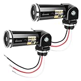
- DUSK TO DAWN PHOTOCELL SENSOR SWITCH -- This photocell sensor switch will automatically turn on lights at dusk and off at dawn. No need for manual operation anymore. The delay feature in the outdoor light sensor prevents the accidental triggering off the light due to the headlights of a passing car or lightning.
- MULTI VOLTAGE SWIVEL PHOTOSENSOR -- Handles between 120V and 277V and compatible with LED, CFL, fluorescent, incandescent and other types of bulbs, so you can use this photoelectric switch sensor in most various occasions such as outdoor lighting, exterior lighting, street lighting, passage lighting, and doorway lighting.
- UL LISTED PHOTOCELL LIGHT SENSOR -- Covered with UL certificate, surge protection available, heavy-duty body, P65 Water-resistant, AC 120-277 input voltage, 50/60Hz, threaded diameter 1.06 inch, 5-20Lx on and 20-60Lx off operate level.
- EASY TO INSTALL -- With a swivel mount, this outdoor light controller can be easily installed it at a precise spot focusing light. Just disconnect power, place screw thread of the SWITCH in the knockout hole and fasten with rubber gasket and zinc alloy lock-nut.
- RELIABLE QUALITY AND SERVICE -- UL listed, 3 year warranty available. Please feel free to contact us for refund or replacement if you have any questions or quality problem about the outdoor photocell sensor. We will response within 24 working hours
Hybrid architecture
A practical municipal retrofit often combines panel-level scheduling and protection with individual controllers for monitoring and dimming. This can be more resilient than a design that depends entirely on cloud connectivity, while still enabling pole-level maintenance information.
Control logic for a dependable installation
A practical state machine can be expressed as follows:
DAY:
    lights OFF
    continue self-test
    detect unexpected current or day-burning

DUSK:
    verify ambient light or astronomical schedule
    turn on to minimum safe level
    confirm electrical and optical response

EVENING_PEAK:
    operate at programmed full or high level

LOW_TRAFFIC:
    reduce to background level
    never go below the approved minimum

MOTION_DETECTED:
    brighten the current zone
    optionally brighten adjacent poles
    hold for configured time
    fade gradually rather than switching abruptly

FAULT:
    record timestamp, pole ID, type, and severity
    retry transient commands
    issue local fallback command
    notify operator if fault persists

COMMUNICATION_LOST:
    use locally stored schedule
    preserve minimum-safe operation
    buffer events
    reconnect and upload history later
Important configurable parameters include ambient-light thresholds and hysteresis, turn-on and turn-off delays, background level, motion hold time, fade-up and fade-down time, neighbouring-pole coordination, fault confirmation period, retry count, heartbeat interval, offline duration, alarm severity, and maintenance acknowledgement rules. These values are installation-specific and should not be copied as universal engineering settings.
Example controller pseudocode
read ambient_lux
read motion
read voltage
read current
read controller_health

if ambient_lux < dusk_threshold:
    enable scheduled lighting

if lighting_enabled:
    if motion_detected:
        set brightness ACTIVE_LEVEL
        start hold_timer
    elif hold_timer expired:
        set brightness BACKGROUND_LEVEL

if lighting_command == ON:
    if current < expected_minimum:
        start fault_timer
    else:
        clear lamp_fault_timer

if fault_timer exceeds confirmation_period:
    create fault("possible open circuit, failed driver, or failed lamp")

if heartbeat_due:
    send pole_id, command_state, measured_current, measured_power,
         brightness, temperature, communication_quality, fault_code

if communication_lost:
    continue local schedule
    store events locally
NEMA versus Zhaga-D4i
Interoperability is a construction and procurement decision, not just a connector choice. Zhaga Book 18 and Zhaga-D4i address interfaces between outdoor LED luminaires and sensing or communications modules. Zhaga notes that interoperability depends on both the luminaire and the module being appropriately certified. Its procurement guidance also references ANSI C136.41 as an outdoor controller and sensor interface option.
| Consideration | ANSI C136.41/NEMA-style controller | Zhaga-D4i node |
|---|---|---|
| Typical position | Upstream of the driver, often on a luminaire receptacle | Integrated with the luminaire and driver/data architecture |
| Power path | May provide mains switching, surge protection, and control | Generally designed around the luminaire’s connected-driver architecture |
| Control | May use 1–10 V, DALI, or switching, depending on equipment | Uses DALI/D4i data and power capabilities where supported |
| Retrofit implication | Useful where existing receptacles and compatible luminaires are available | Requires suitable Zhaga-D4i luminaire and certified node combination |
| Data and metering | Depends on controller and driver capabilities | Can expose standardised driver and luminaire data when the full system supports it |
These are alternative ecosystems with different electrical and mechanical characteristics, not automatically interchangeable plug-and-play standards. Confirm receptacle type, voltage, dimming protocol, metering, surge protection, certification, enclosure requirements, and software compatibility for every luminaire family.
For additional context on controller placement and interface trade-offs, see Schréder’s NEMA and Zhaga-D4i material. Component suppliers such as TE Connectivity also provide receptacle and connector hardware, but components alone are not a turnkey management system.
Prototype versus production roadway deployment
| Prototype | Production system |
|---|---|
| Arduino, LDR, relay, buzzer, Wi-Fi | Certified outdoor controller, driver interface, communications, and management platform |
| Threshold tested on a bench | Commissioned against the lighting plan and environmental conditions |
| Single lamp or small model | Asset IDs, maps, zones, panel coordination, and maintenance records |
| Unprotected low-voltage wiring | Electrical isolation, surge protection, ingress protection, grounding, and qualified installation |
| Binary lamp alarm | Classified faults with severity, timestamps, retries, acknowledgement, and closure |
| Wi-Fi dependency | Local schedule and defined behaviour during network and cloud outages |
Published prototypes are useful for demonstrating concepts, but their reported performance should not be treated as a roadway benchmark. A 2023 open-access prototype used 10 W, 12 V DC LEDs and reported average savings of 53.45%, 44.76%, 39.39%, and 32.25% under different idle-brightness settings. Those figures apply to that prototype and its assumptions, not to a city-wide installation. The study also included wireless communication, movement detection, encrypted settings, and a fail-safe mechanism.
Best Value

- Automatic Performance:this advanced photoelectric switch automatically turns lights on at dusk and off at dawn, eliminating the need for manual operation and making energy savings a breeze
- Precision Circuit Design: Equipped with next-gen light-controlled sensor components and anti-interference programming,it ensures synchronized multi-sensor response with high accuracy and sensitivity
- Durable Weatherproof Construction: The rugged enclosure, crafted from industrial-grade materials, reliably withstands rain and dust, delivering enduring outdoor performance
- Easy Installation: The classic and easy-to-install design saves space while ensuring seamless adaptation to both indoor and outdoor lighting setups
- Widely Application – Ideal for garden lighting, porch lamps, pathway illumination, and other outdoor lighting systems, offering adaptable solutions for diverse needs
A 2025 paper describes an Arduino Uno, LDR, RTC, Wi-Fi module, current sensor, and relay-based fault-alert prototype. A 2026 paper reports prototype-specific claims of approximately 1.5–2 seconds for switching, 500 milliseconds for fault detection, and about 58% energy reduction. These values should be attributed to the respective papers and independently validated before they influence a construction specification.
Independent reader supportYour contribution helps us test, update, and keep practical guides available for everyone.How to calculate energy and financial performance
Start with a measured baseline rather than a headline percentage:
Annual energy = average system power × operating hours × number of luminairesFor a controlled system:
Annual savings = baseline energy
               − controlled-luminaire energy
               − controller, sensor, and network energy
Then include installation, commissioning, software, communications, maintenance visits, replacement parts, training, and financing or service costs. Separate the following effects:
- LED conversion: replacing older lamps with more efficient LED luminaires.
- Schedule improvement: eliminating daytime burning and correcting inaccurate switching.
- Dimming: lowering output during approved low-demand periods.
- Adaptive operation: reducing output when no road users are detected.
- Maintenance savings: fewer inspection trips and faster identification of failed assets.
- System overhead: controller, sensor, gateway, modem, software, and standby energy.
Measure representative circuits before and after installation, record operating hours and dimming levels, and define whether the comparison covers only lamp energy or the complete system. A claim such as 40%, 53%, 58%, or 60% is meaningful only with its baseline, measurement boundary, traffic assumptions, minimum lighting level, weather, and maintenance conditions. For example, the approximately 60% cost-reduction claim in the cited 2025 paper is presented for a proposed Bangladesh deployment model, not as a universal municipal result.
Safety, resilience, and construction requirements
- Keep a locally stored schedule so lights continue operating during communications or cloud outages.
- Define a safe fallback state and provide an authorised manual override.
- Use appropriate electrical isolation between hazardous mains circuits and low-voltage electronics.
- Specify surge protection, grounding, thermal design, outdoor enclosure and ingress protection requirements.
- Protect connectors against moisture, condensation, corrosion, dust, insects, vibration, and salt exposure.
- Account for voltage sag, breaker trips, relay contact welding, driver standby current, and repeated controller resets.
- Use authenticated devices, encrypted communications, role-based access, audit logs, secure credential handling, and signed firmware where supported.
- Define firmware-update recovery so an update cannot leave a road unlit or permanently inaccessible.
- Use qualified personnel for mains installation, testing, and commissioning.
Sensor placement deserves construction supervision. An LDR under a tree or beside a bright sign may produce a different switching result from an exposed reference point. Radar alignment can change after pole work. Door and tilt sensors should be tested after the enclosure, bracket, and pole hardware are complete.
Commissioning and acceptance checklist
Control and lighting
- Verify pole and luminaire asset IDs against the physical labels and GIS or management map.
- Test day/night switching with the installed photocell or astronomical schedule.
- Verify time zone, location, calendar, clock retention, and daylight-saving behaviour where relevant.
- Confirm every programmed dimming level and fade transition.
- Test motion or radar range, zone coordination, hold time, false triggers, and detection of slow or obscured users.
- Confirm the minimum background level and manual override.
Fault and electrical tests
- Disconnect a luminaire and verify the correct pole-level alarm.
- Simulate driver or output-stage failure where safe and supported.
- Trip a breaker or remove panel supply and confirm that the system distinguishes circuit loss from individual-lamp failure.
- Test low voltage, overtemperature, abnormal current, and dimming-related thresholds.
- Open a pole door or activate tilt/tamper inputs.
- Verify alarm severity, retries, timestamp, acknowledgement, assignment, repair, and closure.
Network and recovery tests
- Interrupt cellular, RF, LPWAN, wired, or gateway communications.
- Confirm local schedule operation and local event buffering.
- Restore connectivity and verify historical events upload without duplication.
- Reboot a controller and confirm safe recovery.
- Test cloud or management-platform outage behaviour.
- Test firmware update interruption and recovery.
- Confirm audit logs, access controls, data export, and security alerts.
Procurement questions for owners and contractors
Include these requirements in the tender or technical specification:
- Which physical and electrical interfaces are supported: NEMA/ANSI C136.41, Zhaga-D4i, conduit, DALI, 0–10 V, PWM, relay, or a combination?
- Is control available at panel, zone, and individual-luminaire level?
- Can the system distinguish a lamp, driver, circuit, controller, sensor, and communications fault?
- Does it measure current, real power, voltage, power factor, energy, temperature, and actual dimming level?
- What happens when the network, gateway, cloud, GPS, sensor, or controller fails?
- How are devices authenticated, encrypted, updated, and retired?
- Is there a documented API, export format, event history, and ownership of operational data?
- What are the warranty, firmware-support period, replacement-stock, spare-parts, and local-service arrangements?
- What are the controller, sensor, gateway, installation, commissioning, cellular, software, support, and replacement costs over five and ten years?
- Are claimed energy savings independently measured, and what baseline and minimum lighting levels were used?
- What interoperability certifications apply to the exact luminaire-node combination?
- How will alarms be assigned, acknowledged, repaired, and closed?
Commercial systems illustrate the range of approaches. Signify cellular nodes describe GPS-based commissioning, light sensing, tilt notification, firmware support, and Zhaga, NEMA, and conduit-mounted configurations. Signify outdoor multisensors are positioned for Zhaga-D4i and DALI-connected sensing. Redcoast’s RC-OLC-200 is presented as a controller supporting NEMA and Zhaga-D4i interfaces, metering, dimming, and multiple network options. These are vendor claims and product positions; verify certification, service availability, compatibility, and measured performance in the project proposal.
Quick wins for a faster PC:
Repair Windows errors before they cause bigger problemsFix Now →Fix the driver behind crashes, sound loss and screen glitchesFind Drivers →Public unit and subscription prices were not displayed on the cited official vendor pages as of August 16, 2026. Request a bill of materials, installation scope, recurring service costs, warranty terms, and a five- to ten-year total-cost model rather than comparing hardware prices alone.
Common design mistakes
- Calling a classroom prototype roadway-ready: Arduino, relay, LDR, buzzer, and Wi-Fi do not by themselves address surge immunity, EMC, ingress protection, electrical safety, cybersecurity, maintainability, or lighting compliance.
- Treating current sensing as complete fault detection: current identifies some electrical abnormalities but cannot guarantee useful light output.
- Confusing communication loss with lamp failure: classify the communications alarm separately and retain local operation.
- Ignoring dimming in thresholds: expected current must change with the commanded output level.
- Using presence detection with no background level: unexpected darkness between detections can create safety, comfort, and liability problems.
- Publishing savings without a baseline: percentages need a defined old system, schedule, measurement boundary, and operating conditions.
- Assuming interfaces are interchangeable: verify the exact NEMA, Zhaga-D4i, driver, receptacle, control, and certification combination.
- Stopping at the alarm: detection has little operational value unless the alert is mapped, prioritised, assigned, repaired, acknowledged, and closed.
Bottom line for a construction project
The strongest specification is a standards-aware, locally autonomous lighting system with remote visibility—not merely an automatic relay controlled by an LDR. Use photocells or astronomical schedules for dependable base control, add scheduled dimming where the lighting design permits it, use motion or radar conservatively with a minimum background level, and combine current or power monitoring with driver, optical, sensor, and heartbeat data when individual fault diagnosis matters. Before acceptance, prove safe operation during electrical, sensor, communications, cloud, and firmware failures, then evaluate savings from measured baseline data rather than prototype percentages.
Quick Recap
Product prices and availability are accurate as of the date/time indicated and are subject to change. Any price and availability information displayed on Amazon at the time of purchase will apply.


Leave a Reply