Do these 3 things before closing this tab:
1Fix the driver behind crashes, sound loss and screen glitches2Repair Windows errors before they cause bigger problems3Scan for outdated or missing drivers - takes under a minuteSome links on this page are affiliate links: if you buy through them we may earn a commission, at no extra cost to you.
An Arduino water-level display combines a sensor, an Arduino Uno, and a 16×2 or 20×4 character LCD. The sensor may send an analog signal to A0, while the LCD uses the Uno’s I2C bus on A4 (SDA) and A5 (SCL). The Arduino calibrates the sensor’s raw reading and displays a normalized percentage, estimated height, and status such as LOW, MEDIUM, or HIGH.
This guide builds the simplest version with a conductive analog sensor, then explains when a waterproof ultrasonic or non-contact capacitive sensor is a better choice for a tank or permanent installation.
How the water-level display works
Water-level sensor → Arduino input → calibration and filtering → percentage/status
                                      ↓
                                I2C LCD display
The display can show several different meanings of “level”:
The Tool Desk
Outbyte Driver Updater FREEFix the driver behind crashes, sound loss and screen glitchesFind Drivers →Outbyte PC Repair FREEClear out junk files and repair common Windows errorsFree Scan →- Raw sensor value: the ADC number returned by
analogRead(). - Normalized level: a calibrated value from 0 to 100 percent.
- Physical height: an estimated water height in centimetres.
- Tank fullness: a percentage based on measured empty and full conditions.
- Threshold status: a label such as LOW, MEDIUM, or HIGH.
A raw Arduino reading is not automatically a percentage. Calibration is required, and a level percentage is not necessarily a true volume percentage in an irregular or horizontal tank.
#1 Best Overall
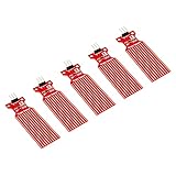
- Used to detect the presence of water, water leakage
- Used to measure the water level
- Supply voltage: 3.3 - 5V DC. Current consumption: less than 20mA
- Water sensor for Arduino, ESP32, ESP8266, Raspberry Pi, or any 5V or 3.3V microcontroller.
- Tutorials for Arduino, ESP32, ESP8266 and Raspberry Pi are provided => search for: DIYables Water Sensor
Choose the right sensor
| Requirement | Recommended sensor | Important limitation |
|---|---|---|
| Low-cost classroom demonstration | Conductive analog sensor | Probe corrosion and water-conductivity effects |
| Single wet/dry threshold | Digital capacitive sensor | Usually not a continuous percentage meter |
| Continuous, non-contact tank measurement | Waterproof ultrasonic sensor | Needs a clear acoustic path and sufficient minimum range |
| Sealed or chemically aggressive container | Non-contact capacitive sensor | Verify its output; many are digital point detectors |
| Long-term or safety-critical monitoring | Industrial ultrasonic, pressure, radar, or capacitive transmitter | Higher cost and installation complexity |
Conductive analog sensor
A typical inexpensive probe module exposes conductive traces to the water and produces an analog signal. It is easy to connect and suitable for open containers, short experiments, and learning projects. Its reading changes with water conductivity, immersion depth, orientation, supply voltage, and sensor construction. The exposed traces can also corrode, especially when continuously powered with DC.
Use this type as an educational sensor rather than a precision or unattended tank instrument. An example Arduino project uses a water sensor on an analog input with an I2C LCD: Arduino Project Hub Smart Dispenser.
Waterproof ultrasonic sensor
An ultrasonic sensor measures the distance from a transducer above the tank to the water surface. A waterproof Arduino-listed sensor is specified for 3.0–5.5 V operation, a 20 cm to 6 m operating range, 1 mm stated resolution, and 30 mA operating current. Those specifications apply to that particular model, not to every HC-SR04-style module. See the manufacturer’s product page.
Quick wins for a faster PC:
Repair Windows errors before they cause bigger problemsFix Now →Scan for outdated or missing drivers - takes under a minuteDriver Scan →Clear out junk files and repair common Windows errorsFree Scan →As the tank fills, the measured distance decreases:
waterHeight = emptyDistance - measuredDistance
levelPercent = 100 × waterHeight / usableTankHeight
Mount the sensor vertically above the maximum water level. Foam, splashing, condensation, turbulence, narrow walls, and the sensor’s minimum range can cause false or unstable readings. A bare indoor HC-SR04 is not waterproof.
Non-contact capacitive sensor
A non-contact sensor can detect liquid through a container wall, making it useful for sealed containers or liquids that should not touch a probe. The Arduino Gravity model is described as using the XKC-Y25-T12V signal-processing chip, but it is a digital level detector, not automatically a continuous analog height sensor. Confirm the module’s output behaviour before designing a multi-level percentage display. See the Arduino product description.
Parts for the beginner circuit
- Arduino Uno Rev3 or compatible 5 V board
- 16×2 I2C character LCD
- Analog water-level sensor
- Breadboard and jumper wires
- USB cable and Arduino IDE
A 20×4 LCD is useful when you want to show raw value, percentage, height, and alarm state together. Keep the Arduino and LCD electronics above the tank and protected from splashes.
Rank #2

- A float switch is a device used to sense the level of liquid within a tank, it may actuate a pump, an indicator, an alarm, or other device.
- Use them with hydroponics, saltwater tank, freshwater tank, gardening, aquariums for power head control, pet bowls, fish tanks, filtration, heating etc.
- Good quality, Not easily damaged and good quality.
- Package Indluced:3 pc Water Level Sensor Horizontal PP Side Mount Float Switch For Tank Pool Arduino
- Thank you so much for your purchasing from our store.Any question ,please feel free to contact us.
Wire the sensor and I2C LCD
On an Arduino Uno Rev3, use this wiring:
| Component | Pin | Arduino Uno |
|---|---|---|
| Water-level sensor | S or signal |
A0 |
| Water-level sensor | + or VCC |
5V |
| Water-level sensor | - or GND |
GND |
| LCD backpack | VCC | 5V |
| LCD backpack | GND | GND |
| LCD backpack | SDA | A4 |
| LCD backpack | SCL | A5 |
The LCD’s I2C connection and the sensor’s signal connection are separate. “I2C LCD” does not mean that the water sensor also communicates over I2C. Nano boards based on the same ATmega328P arrangement typically use A4 and A5 too, but other Arduino families may expose I2C on different labelled pins. Check the board pinout.
Confirm that the module labels mean VCC, ground, and signal. A 3.3 V board may not tolerate a 5 V sensor or LCD pull-up; verify voltage limits and use level shifting where necessary.
Find the LCD address
0x27 is common, but it is not universal. Some backpacks use 0x3F or another address. Upload this scanner before troubleshooting the LCD:
#include <Wire.h>

void setup() {
  Serial.begin(9600);
  Wire.begin();
  Serial.println("I2C scanner");

  for (byte address = 1; address < 127; address++) {
    Wire.beginTransmission(address);
    byte error = Wire.endTransmission();

    if (error == 0) {
      Serial.print("Found I2C device at 0x");
      if (address < 16) Serial.print("0");
      Serial.println(address, HEX);
    }
  }
}

void loop() {}
Open the Serial Monitor at 9600 baud. If it reports 0x3F, replace 0x27 in the LCD object. If it finds nothing, check power, common ground, SDA/SCL orientation, solder joints, and cable length.
Install a compatible LCD library
In Arduino IDE, open Tools → Manage Libraries and install the exact library required by your sketch. Arduino documents similarly named libraries including LiquidCrystal_I2C, LCD-I2C, and LiquidCrystal I2C. Their APIs are not guaranteed to be interchangeable.
The sketch below targets a common LiquidCrystal_I2C API. If lcd.init() does not compile, open the installed library’s example and use its initialization form, which may be lcd.begin(16, 2) or lcd.begin().
Calibrate empty and full readings
- Remove the sensor from the water, or place it at the defined empty position.
- Open the Serial Monitor and record the stable empty reading.
- Place the sensor at the intended full-water position.
- Record the stable full reading.
- Replace
EMPTY_READINGandFULL_READINGin the sketch. - Test several intermediate levels.
- Confirm whether the value rises or falls as the water rises.
The calculation is:
percentage = 100 × (raw − emptyReading) / (fullReading − emptyReading)The result is clamped to 0–100 so readings outside the calibration points do not produce impossible percentages. Calibration values from another sensor or another liquid should not be copied.
Rank #3

- The CQRobot non-contact liquid level sensor realizes non-contact detection of the liquid level in a closed container. It adopts advanced signal processing technology and high-speed signal processing chip, breaking through the influence of container wall thickness. It is simple to install and easy to use, and can detect the level of various toxic substances, strong acids, strong alkalis and various liquids in high-pressure airtight containers.
- The principle is to use the inductive capacitance of water to detect whether there is liquid. When there is no liquid close to the sensor, the sensor has a certain static capacitance to the ground due to the existence of distributed capacitance on the sensor. When the liquid level slowly rises and approaches In the case of an inductor, the parasitic capacitance of the liquid will be coupled to this static capacitance, making the final capacitance value of the inductor larger.
- The changed capacitance signal is then input to the control IC for signal conversion, which converts the changed capacitance into a change of a certain electrical signal, and then a certain algorithm is used to detect and judge the degree of this change. When the change exceeds a certain amount It is considered that the liquid level has reached the sensing point when the threshold is reached.
- High stability, high sensitivity, strong interference ability, no external electromagnetic interference, special treatment for power frequency interference and common mode interference, strong compatibility, penetration of various non-metallic containers, such as plastic, glass, For ceramics and other containers, the sensing distance can reach more than 12mm; liquid, powder, and particulate matter can be detected.
- The sensor comes with 2 DIP switches, the right DIP switch controls the output voltage (high level) of the signal terminal (green line); when the DIP switch is dialed up, the high level is 5V; when the DIP switch is facing When dialing down, the high level is 3.3V. Compatible with Arduino, Raspberry Pi and Other Motherboards.
Complete Arduino sketch
#include <Wire.h>
#include <LiquidCrystal_I2C.h>

const byte SENSOR_PIN = A0;

// Replace 0x27 with the address found by the scanner.
LiquidCrystal_I2C lcd(0x27, 16, 2);

// Replace these with your measured calibration values.
const int EMPTY_READING = 120;
const int FULL_READING  = 760;
const byte SAMPLE_COUNT = 10;

int readAveragedSensor() {
  long total = 0;

  for (byte i = 0; i < SAMPLE_COUNT; i++) {
    total += analogRead(SENSOR_PIN);
    delay(5);
  }

  return total / SAMPLE_COUNT;
}

void setup() {
  Serial.begin(9600);

  lcd.init();       // Some libraries use lcd.begin() instead.
  lcd.backlight();
  lcd.clear();

  lcd.setCursor(0, 0);
  lcd.print("Water level");
  delay(1000);
}

void loop() {
  int raw = readAveragedSensor();

  int percent = map(raw, EMPTY_READING, FULL_READING, 0, 100);
  percent = constrain(percent, 0, 100);

  const char* status;

  if (percent < 30) {
    status = "LOW";
  } else if (percent < 70) {
    status = "MEDIUM";
  } else {
    status = "HIGH";
  }

  lcd.setCursor(0, 0);
  lcd.print("Level: ");
  if (percent < 100) lcd.print(" ");
  if (percent < 10)  lcd.print(" ");
  lcd.print(percent);
  lcd.print("% ");

  lcd.setCursor(0, 1);
  lcd.print("Status: ");
  lcd.print(status);
  lcd.print("       ");

  Serial.print("Raw: ");
  Serial.print(raw);
  Serial.print("  Level: ");
  Serial.print(percent);
  Serial.print("%  Status: ");
  Serial.println(status);

  delay(500);
}
The display refreshes twice per second, which is “real-time” only in the practical hobby-project sense of repeatedly updating the reading. It does not make the sensor industrially accurate or suitable for safety-critical control.
Display height instead of—or as well as—percentage
If the calibrated usable tank height is known, convert the normalized result to an estimated height:
const float TANK_HEIGHT_CM = 35.0;
float heightCm = (percent / 100.0) * TANK_HEIGHT_CM;
For a 16×2 display, replace the second-line output with:
lcd.setCursor(0, 1);
lcd.print(heightCm, 1);
lcd.print(" cm        ");
This is an estimate based on empty/full calibration. It is not a direct physical measurement unless the sensor and installation are designed and calibrated for that purpose.
If the sensor value decreases as the water rises, reverse the mapping:
int percent = map(raw, FULL_READING, EMPTY_READING, 100, 0);
percent = constrain(percent, 0, 100);
Improve stability and reliability
Reduce noisy readings
The example averages ten samples. For more difficult signals, use a moving median or an exponential filter:
filtered = (filtered * 0.8) + (newReading * 0.2);Filtering smooths the display; it does not correct poor calibration, corrosion, bad placement, or a sensor that is unsuitable for the liquid.
Rank #4

- Contact Water/Liquid Level Sensor, This is a photoelectric water liquid level sensor that is operates using optical principles. Open collector output mode, suitable for connecting various circuits and product applications.
- The sensor has no mechanical parts, requires no additional adjustment, and has high sensitivity, low power consumption, corrosion resistance, high pressure resistance, high temperature resistance and chemical stability.
- This sensor probe is small in size and has a structure that can be placed up, down, laterally, and diagonally in multiple orientations to detect solution spillage, dryness and horizontal level. Can be used as a reminder and alarm function.
- The sensor has a DIP switch. The DIP switch controls the output voltage (high level) of the signal terminal (green line). When the DIP switch is dialed to 5V, the high level is 5V. When the DIP switch is dialed At 3V, the high level is 3.3V.
- Compatible with Arduino motherboard and Raspberry Pi motherboard. for Automatic Irrigation Systems, Aquariums, Plants, in The Garden, in Agriculture etc.
Prevent status flicker
Use hysteresis around thresholds. For example, change to LOW below 25 percent, but do not leave LOW until the reading exceeds 30 percent. This prevents small fluctuations from repeatedly changing the displayed status.
Limit conductive-probe corrosion
- Power the probe only while taking a reading.
- Sample infrequently rather than continuously.
- Consider alternating polarity instead of applying continuous DC.
- Use a capacitive or ultrasonic sensor for a permanent installation.
These measures may slow corrosion; they do not turn an inexpensive conductive probe into a long-term precision instrument.
PC Slower Than It Used to Be?
A free scan shows the junk files, broken settings and background clutter dragging Windows down - then fixes them in one click.Free scan · Windows 10 & 11Crashes, No Sound, or Screen Glitches?
Random freezes, missing sound and display glitches usually trace back to one bad driver. Find and replace yours safely.Free scan · under a minuteHandle tank turbulence
For ultrasonic measurement, average multiple readings, reject impossible jumps, use a stilling tube or calm section where appropriate, and avoid measuring immediately after a pump starts or stops. If no valid echo is received, display ERR or NO ECHO rather than a false percentage.
Ultrasonic sensor alternative
The LCD wiring and library remain the same, but the sensor input changes from analogRead() to trigger-and-echo timing:
const byte TRIG_PIN = 9;
const byte ECHO_PIN = 10;

unsigned long duration;
float distanceCm;

digitalWrite(TRIG_PIN, LOW);
delayMicroseconds(2);
digitalWrite(TRIG_PIN, HIGH);
delayMicroseconds(10);
digitalWrite(TRIG_PIN, LOW);

duration = pulseIn(ECHO_PIN, HIGH, 30000UL);

if (duration == 0) {
  // No echo received: treat the reading as invalid.
} else {
  distanceCm = duration * 0.0343 / 2.0;
}

const float EMPTY_DISTANCE_CM = 80.0;
const float FULL_DISTANCE_CM  = 15.0;

float levelPercent =
  100.0 * (EMPTY_DISTANCE_CM - distanceCm) /
  (EMPTY_DISTANCE_CM - FULL_DISTANCE_CM);

levelPercent = constrain(levelPercent, 0.0, 100.0);
The subtraction is reversed because a fuller tank produces a smaller distance. Replace the empty and full distances with measurements from the actual installation, and ensure the tank fits within the sensor’s specified range.
Troubleshooting
The LCD is blank
- Run the I2C scanner and verify the address.
- Check SDA and SCL wiring.
- Confirm power and common ground.
- Turn the backpack contrast potentiometer slowly.
- Test a minimal “Hello” LCD sketch.
- Check whether your library requires
init()orbegin().
The LCD shows blocks only
Power and contrast are probably present, but initialization is failing. Check the address, library compatibility, backpack soldering, SDA/SCL wiring, and board voltage.
Recommended Free Tools
The percentage is wrong
Recalibrate empty and full conditions. Check sensor orientation, immersion depth, supply voltage, water conductivity, and whether the reading rises or falls with water level. A copied calibration number is rarely reliable.
Best Value

- Accurately measure water level and detect rainwater drops with this high-quality Water Level Sensor, designed for easy integration with development boards.
- Simple to use and cost-effective, this Water Level Sensor features a parallel wire trace design to accurately measure water quantity, providing analog output for easy integration with development boards.
- With a working voltage of DC3-5V and low power consumption of less than 20mA, this Water Level Sensor is an efficient and reliable choice for water level detection and alarm systems.
- The sensor's FR4 double-sided tin-spraying and electronic component manufacturing process ensures durability and reliability, making it suitable for a wide range of applications and environments.
- This Water Level Sensor operates in temperatures ranging from 10°C to 30°C and with a humidity range of 10% to 90% without condensation, providing accurate and consistent water level detection.
The status flickers
Increase averaging, slow the display update, or add hysteresis to the thresholds.
The ultrasonic sensor reports no echo
Check the trigger and echo pins, timeout handling, mounting angle, minimum range, condensation, foam, and whether the beam is striking a tank wall.
The displayed percentage does not equal volume
In a cylindrical vertical tank, height and volume may be approximately proportional. In a horizontal cylinder or irregular reservoir, they are not. For accurate volume, create a calibration table that maps measured height to actual volume.
What’s actually slowing this PC down?
Pick the symptom - the matching free tool is one click away.
When to upgrade the design
Keep the conductive analog sensor for a quick demonstration or short-term open-container project. For a tank, outdoor installation, or non-contact requirement, a waterproof ultrasonic sensor is usually the more suitable hobby upgrade. A non-contact capacitive detector is useful when you need a sealed-wall point-level signal, but verify that it can provide the continuous data your display requires.
For unattended, chemically aggressive, drinking-water, industrial, or safety-critical applications, use a properly rated sensor and enclosure. Do not connect a mains pump directly to an Arduino. Pump automation requires an appropriately rated relay or MOSFET, fuse, flyback protection where applicable, isolation, enclosure, and safe mains wiring.
The project concept—reading a water-level sensor and presenting a normalized value and status on an I2C LCD—is also demonstrated by Visuino’s Arduino water-level display project. The key engineering decisions remain sensor selection, calibration, installation, and handling invalid readings.
Quick Recap
Product prices and availability are accurate as of the date/time indicated and are subject to change. Any price and availability information displayed on Amazon at the time of purchase will apply.


Leave a Reply