Crashes, No Sound, or Screen Glitches?
Random freezes, missing sound and display glitches usually trace back to one bad driver. Find and replace yours safely.Free scan · under a minutePC Slower Than It Used to Be?
A free scan shows the junk files, broken settings and background clutter dragging Windows down - then fixes them in one click.Free scan · Windows 10 & 11Some links on this page are affiliate links: if you buy through them we may earn a commission, at no extra cost to you.
An Arduino can automate a fan when temperature rises, but it should not power a medium- or high-current fan directly from an I/O pin. The reliable arrangement is an Arduino temperature sensor and control circuit, a separate power supply for the fan, and a suitable relay or MOSFET between them.
For most workshop, equipment-enclosure, and construction-site monitoring projects, the best starting point is a DS18B20 sensor, a 5 V Arduino-compatible board, a logic-level MOSFET, and a separately powered 12 V DC fan. Use a relay if you only need on/off ventilation. Use a four-wire PWM PC fan if you need quieter, variable-speed cooling.
First decide what “temperature-controlled” means
These projects are often described as fan controllers even though they perform different jobs:
| Design | What it does | Best use |
|---|---|---|
| On/off control | Turns the fan fully on above one temperature and off below another | Cabinet ventilation, equipment cooling, and simple workshop projects |
| Two-wire DC fan with MOSFET | Switches fan power and may vary speed with PWM | Low-voltage DC fans where silent operation matters |
| Four-wire PWM fan | Supplies the fan continuously and controls speed through its dedicated PWM input | Computer-style or server-enclosure cooling |
A relay provides on/off operation only. It cannot provide continuous speed control. A MOSFET can switch a two-wire DC fan silently and may support power-side PWM, but the fan must tolerate that method. A four-wire PC fan is normally the most predictable choice for variable-speed control, provided its datasheet and pinout are followed.
#1 Best Overall

- Voltage: 5VDC, Current: 0.13A, Power consumption: 0.65W
- DC Brushless Fan: Quiet
- Small size and light weight: 50mm x 50mm x 10mm, 65g
- Tutorials for Arduino, ESP32, ESP8266 and Raspberry Pi are provided
- Cooling Fan works with Arduino, ESP32, ESP8266, Raspberry Pi, or any 5V or 3.3V microcontroller.
Recommended beginner build
The circuit below uses a DS18B20, an Arduino UNO-compatible 5 V board, a logic-level N-channel MOSFET, and a 12 V DC fan. It can be used for ventilation around low-voltage equipment, an enclosure, or a workshop installation. Do not use it to switch mains equipment.
Parts
- Arduino UNO-compatible 5 V board, such as an UNO R4 Minima or compatible board
- DS18B20 temperature sensor, preferably a probe version for remote placement
- 4.7 kΩ resistor
- Logic-level N-channel MOSFET rated for the fan voltage and current
- 12 V DC fan
- 12 V adapter rated above the fan’s operating and startup-current requirement
- Flyback diode suitable for the fan circuit
- Optional 100–220 Ω gate resistor
- Optional 10 kΩ gate pulldown resistor
- Breadboard for testing, or screw terminals and an enclosure for permanent installation
Check the MOSFET’s on-resistance at the actual Arduino gate voltage. A transistor that performs well with a 10 V gate drive may not switch efficiently from a 5 V or 3.3 V output.
Wiring
Connect the DS18B20 as follows:
- VDD to Arduino 5 V
- GND to Arduino GND
- Data to digital pin 2
- 4.7 kΩ resistor between Data and 5 V
Connect the fan driver as a low-side switch:
- 12 V adapter positive to the fan positive lead
- Fan negative lead to the MOSFET drain
- MOSFET source to the 12 V adapter negative terminal
- Arduino GND to the 12 V adapter negative terminal
- Arduino pin 9 through the optional gate resistor to the MOSFET gate
- 10 kΩ pulldown resistor between the gate and ground
- Flyback diode across the fan terminals, with its cathode toward the positive supply
The common ground is required for a typical non-isolated MOSFET circuit. Keep the high-current fan wiring short and separate from delicate sensor wiring where practical.
Fan wire colors, MOSFET pin order, diode markings, and module terminal labels are not universal. Confirm each against the manufacturer’s documentation before applying power. The DS18B20 pull-up arrangement is also documented in this DS18B20 cooling-system example.
Choosing the sensor and Arduino board
| Sensor | Advantages | Limitations | Suitable application |
|---|---|---|---|
| DS18B20 | Digital output, probe versions, remote placement, one-wire bus | Needs a pull-up resistor and libraries | Best general-purpose choice |
| DHT22/AM2302 | Measures temperature and humidity | Slower readings and requires invalid-reading handling | Rooms and spaces where humidity matters |
| DHT11 | Cheap and easy to obtain | Lower accuracy and more limited performance | Basic demonstrations |
| LM35/TMP36 | Simple analog interface | More sensitive to wiring noise and calibration | Introductory analog projects |
| Thermistor | Inexpensive and flexible | Needs a voltage-divider calculation and calibration | Custom low-cost systems |
Use an UNO-compatible 5 V board for breadboard instruction. A Nano-family board is more convenient when the finished controller must fit inside an enclosure. Current board specifications and families are listed on Arduino’s hardware page. Wi-Fi capability is unnecessary unless the project also needs remote monitoring or alerts.
Install the libraries and test the sensor first
In the Arduino IDE, open Sketch > Include Library > Manage Libraries. Install:
Rank #2

- The 30mm fan with 2pin interface connected to the pi motherboard, providing a good cooling effect for Raspberry Pi, The 30x30x7mm computer fan size is 30mm, making it easy to install
- 3007 cooling fan run smoothly(15.92dBA), Long life (30,000 hours) keep CPU safe without overheating
- 30mm case fan unique terminal interface with two terminals, Its connector is separating, 1-to-2 interface connector Interface for dual speed mode (3.3V and 5V DC)
- 3007 case fan compatible with Raspberry Pi B, B+, A+, 2, 3, 4 5 model B and B+ and Pi Zero/Zero W other robotic projects and development boards
- This fan can be installed for most of the standard Raspberry Pi cases and also is compatible with RetroFlag NESPI Case
- OneWire
- DallasTemperature
Test the sensor before connecting the fan. Open the Serial Monitor at 9600 baud and confirm that the displayed temperature is plausible for the sensor’s location. This separates sensor and library problems from power-driver problems.
Quick wins for a faster PC:
Fix the driver behind crashes, sound loss and screen glitchesFind Drivers →Repair Windows errors before they cause bigger problemsFix Now →If using a DHT22, install the appropriate DHT sensor library and its required dependency through Library Manager. Allow at least about two seconds between readings and handle failed or NaN results; the documented DHT cooling-system example demonstrates this approach.
Option 1: reliable on/off control with hysteresis
Use two thresholds rather than one. In this example, the fan turns on at 30 °C but remains on until the temperature falls to 27 °C. The 3 °C gap is hysteresis. It prevents rapid switching when the reading fluctuates around a single threshold.
#include <OneWire.h>
#include <DallasTemperature.h>

const byte SENSOR_PIN = 2;
const byte FAN_PIN = 8;

const float FAN_ON_TEMP  = 30.0;
const float FAN_OFF_TEMP = 27.0;

OneWire oneWire(SENSOR_PIN);
DallasTemperature sensors(&oneWire);

bool fanOn = false;

void setup() {
  Serial.begin(9600);
  sensors.begin();

  pinMode(FAN_PIN, OUTPUT);
  digitalWrite(FAN_PIN, LOW);
}

void loop() {
  sensors.requestTemperatures();
  float temperatureC = sensors.getTempCByIndex(0);

  if (temperatureC == DEVICE_DISCONNECTED_C) {
    Serial.println("Temperature sensor disconnected");
    digitalWrite(FAN_PIN, LOW);
    fanOn = false;
    delay(1000);
    return;
  }

  if (!fanOn && temperatureC >= FAN_ON_TEMP) {
    fanOn = true;
  }

  if (fanOn && temperatureC <= FAN_OFF_TEMP) {
    fanOn = false;
  }

  digitalWrite(FAN_PIN, fanOn ? HIGH : LOW);

  Serial.print("Temperature: ");
  Serial.print(temperatureC);
  Serial.print(" C, Fan: ");
  Serial.println(fanOn ? "ON" : "OFF");

  delay(1000);
}
The example treats a sensor failure as “fan off” for simplicity. For unattended electronics cooling, a safer policy is normally to treat an invalid reading as a fault and run the fan at full or high speed while reporting the fault.
Using a relay module
A properly driven relay module can replace the MOSFET for simple on/off operation. It must be a module designed for the Arduino’s logic level; do not connect a bare relay coil directly to an I/O pin. Relays click, switch more slowly, wear mechanically, and are unsuitable for rapid PWM.
Do these 3 things before closing this tab:
1Repair Windows errors before they cause bigger problems2Scan for outdated or missing drivers - takes under a minute3Clear out junk files and repair common Windows errorsSome relay modules are active-low. If the fan operates opposite to the program, invert the output logic—for example, use LOW for on and HIGH for off—without changing the temperature thresholds.
Rank #3

- High Quality -- 100% brand new and in good condition,with high quality ,great performance
- Super Quiet -- Cooling fan run smoothly(15.92dBA), Long life (30,000 hours) keep CPU safe without overheating
- Unique Terminal Interface -- with two terminals, Its connector is separating, One-to-Two interface connector Interface for dual speed mode (3.3V and 5V DC)
- Compatible with Raspberry Pi B, B+, A+, 2, 3, 4 model B and B+ and Pi Zero/Zero W other robotic projects and development boards
- This fan can be installed for most of the standard Raspberry Pi cases and also is compatible with RetroFlag NESPI Case
Option 2: variable speed with a two-wire DC fan
A MOSFET can apply PWM to a two-wire DC fan. The temperature is mapped to a duty cycle: below the starting temperature the fan is off; as temperature rises, speed increases; at the upper temperature it reaches full duty.
#include <OneWire.h>
#include <DallasTemperature.h>

const byte SENSOR_PIN = 2;
const byte FAN_PWM_PIN = 9;

const float START_TEMP = 28.0;
const float FULL_TEMP  = 40.0;

const int MIN_DUTY = 90;
const int MAX_DUTY = 255;

OneWire oneWire(SENSOR_PIN);
DallasTemperature sensors(&oneWire);

void setup() {
  Serial.begin(9600);
  sensors.begin();
  pinMode(FAN_PWM_PIN, OUTPUT);
  analogWrite(FAN_PWM_PIN, 0);
}

void loop() {
  sensors.requestTemperatures();
  float temperatureC = sensors.getTempCByIndex(0);

  if (temperatureC == DEVICE_DISCONNECTED_C) {
    analogWrite(FAN_PWM_PIN, 0);
    Serial.println("Sensor error: fan off");
    delay(1000);
    return;
  }

  int duty;

  if (temperatureC <= START_TEMP) {
    duty = 0;
  } else if (temperatureC >= FULL_TEMP) {
    duty = MAX_DUTY;
  } else {
    duty = map(
      (long)(temperatureC * 10),
      (long)(START_TEMP * 10),
      (long)(FULL_TEMP * 10),
      MIN_DUTY,
      MAX_DUTY
    );
  }

  analogWrite(FAN_PWM_PIN, duty);

  Serial.print("Temperature: ");
  Serial.print(temperatureC);
  Serial.print(" C, PWM duty: ");
  Serial.println(duty);

  delay(1000);
}
MIN_DUTY is only a starting value. A fan may stall, buzz, or fail to start at a duty cycle where it can continue running once already moving. Test the fan and raise the minimum until startup is reliable. An optional short full-power startup pulse can improve starting performance.
PWM frequency and pin behavior vary between Arduino boards and pins. Some two-wire fans respond well to power-side PWM; others produce noise or behave poorly. If smooth and quiet control is important, use a four-wire PWM fan instead.
Free tools Windows power users keep installed
One-click scans. No signup required.
Option 3: four-wire PWM PC fan
A typical four-wire fan has:
- Supply voltage
- Ground
- Tachometer output
- Dedicated PWM control input
The fan remains powered from its rated supply, while the Arduino controls the PWM input. Do not assume that an ordinary Arduino PWM pin is automatically electrically compatible. Check the fan documentation for its required PWM frequency and voltage, whether the input expects an open-collector or open-drain driver, behavior when the control wire is disconnected, minimum duty cycle, and tachometer output characteristics.
The documented four-pin fan controller project is a useful reference for configurable temperature limits, hysteresis, and duty-cycle values. Its pin assignments and control values should not be copied without checking the selected fan. An Arduino forum example also demonstrates a DS18B20-based four-wire controller with these configurable features.
Set thresholds for the equipment, not by habit
There is no universal “fan on at 30 °C” setting. Choose thresholds based on what is being cooled, its permitted operating temperature, sensor position, airflow, ambient conditions, and acceptable noise. Place the sensor where temperature matters—for example, near a heat-producing controller or inside the upper part of an enclosure—not directly in the fan’s outlet stream.
Rank #4

- Hypro sleeve fan suitable for Raspberry Pi 4 and 3 model B and B+,
- One-to-Two wire connector Interface for dual speed mode (3.3V and 5V DC)
- Low noise (15.92dBA), Long life (30,000 hours)
- Compatible with other robotic projects and development boards
For relay systems, add hysteresis and consider a minimum on/off dwell time if temperature changes quickly. For PWM systems, define a minimum running duty, maximum duty, and an over-temperature behavior that overrides the normal curve.
Recommended Free Tools
Testing and calibration checklist
- Power the Arduino and confirm a plausible sensor reading.
- Check the fan’s rated voltage and current from its label or datasheet.
- Verify the adapter voltage matches the fan voltage and its current rating exceeds the fan’s demand, including startup.
- Test just below the fan-on threshold.
- Warm the sensor deliberately and confirm the fan starts.
- Cool the sensor and confirm hysteresis prevents immediate cycling.
- Test fan startup at the selected minimum PWM duty.
- Disconnect the sensor and confirm the chosen fail-safe behavior.
- Watch for Arduino resets, excessive MOSFET heating, buzzing, or unstable readings.
Troubleshooting
The fan does not run
Confirm that the fan has a separate, correctly rated supply; the adapter can provide startup current; the Arduino and external supply share ground in the MOSFET circuit; and the MOSFET pinout is correct. For a relay, verify whether the module is active-high or active-low. Never test a 12 V fan from an Arduino 5 V pin or GPIO pin.
The Arduino resets when the fan starts
Startup current may be pulling the supply voltage down, or motor noise may be entering the Arduino’s power and ground wiring. Use a separate fan supply, keep high-current paths short, improve grounding, and add suitable supply decoupling near the controller and driver.
The fan always runs at full speed
A relay can only produce on/off operation. With a MOSFET, check that PWM is being written to the correct pin and that the gate is wired correctly. With a four-wire fan, confirm that PWM is connected to the control input rather than the supply lead and that the electrical interface and frequency meet the fan specification.
The fan stalls or buzzes
The duty cycle may be too low, the PWM frequency may be unsuitable, or the fan may not support power-side PWM. Increase the minimum duty, add a startup boost, or change to a four-wire PWM fan.
What’s actually slowing this PC down?
Pick the symptom - the matching free tool is one click away.
The temperature is wrong or missing
Check DS18B20 polarity, the data wire, the 4.7 kΩ pull-up resistor, library installation, and sensor placement. Avoid placing the sensor where heat travels through its leads or where fan airflow gives a misleadingly low reading. Always handle disconnected and invalid readings in software.
Best Value
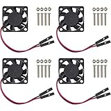
- Hypro sleeve fan suitable for Raspberry Pi 5, Pi 4 and Pi 3 B+.
- One-to-Two wire connector Interface for dual speed mode (3.3V and 5V DC)
- Low noise (15.92dBA), Long life (30,000 hours)
- Compatible with other robotic projects and development boards
The relay clicks repeatedly
This is usually threshold chatter. Use separate on and off temperatures, average several readings, or impose a minimum time between state changes.
Safety and permanent installation
Keep the beginner circuit to low-voltage DC. Do not put exposed mains voltage on a breadboard or treat an AC mains fan like a 12 V motor. A mains installation needs an appropriately rated, enclosed, isolated switching arrangement and competent electrical work.
For a permanent construction-site or equipment installation, use a suitable enclosure, protected terminals, strain relief, cable glands, a correctly rated adapter, and an inline fuse where appropriate. Keep cables and loose parts away from fan blades. A breadboard is for development, not a durable final installation exposed to vibration, dust, moisture, or accidental contact.
When Arduino is not the best solution
A ready-made thermostat switch is often better for basic on/off ventilation without logging or customization. A dedicated PC fan controller is more appropriate for several four-wire fans, tachometer monitoring, and mature fan-control behavior. Choose an ESP32 or another network-capable board only when remote dashboards, alerts, or configuration are needed. For unattended or safety-critical thermal regulation, use a dedicated commercial temperature controller rather than relying on a hobby prototype alone.
Optional improvements include an OLED or LCD display, buttons or a potentiometer for threshold adjustment, an RGB status LED, a buzzer for over-temperature alarms, EEPROM storage for settings, and tachometer feedback. Arduino Project Hub examples show how displays, adjustable references, indicators, and packaged kit components can be incorporated, but their wiring should be treated as project-specific rather than universal.
Quick Recap
Product prices and availability are accurate as of the date/time indicated and are subject to change. Any price and availability information displayed on Amazon at the time of purchase will apply.


Leave a Reply