Some links on this page are affiliate links: if you buy through them we may earn a commission, at no extra cost to you.
You can build a clap-controlled light prototype with an ESP32, a microphone module, and a low-voltage output. The reliable way to start is to make the ESP32 switch an LED, then add an appropriately rated, enclosed switching device only if you know how to install it safely. A common KY-038-style sensor does not identify claps: it detects sound crossing a threshold, so a knock, dropped object, or loud speech can trigger it too. A two-clap timing rule makes the prototype more selective, but cannot eliminate false triggers.
How the clap switch works
The sensor converts sound into an electrical signal. The ESP32 reads that signal, looks for a short increase above the room-noise baseline, and checks whether a second event arrives within a set time. If the pattern matches, it toggles an LED or a low-voltage load.
Clap → microphone/sound sensor → ESP32 detection and timing → LED or suitable driver → lightThis is sound-impulse detection, not speech recognition or dependable acoustic classification. Even a two-clap pattern can be imitated by other noises. A KY-038-style board usually provides an analog output and a comparator-based digital output; its digital output indicates that sound crossed an adjustable threshold, not that the sound was specifically a clap. The exact output polarity and behavior can vary among module versions. See an example sound-detection module description.
Recommended Free Tools
Parts for a low-voltage prototype
- An ESP32 development board.
- A microphone amplifier or sound-sensor module with an analog output.
- An LED and suitable current-limiting resistor for the first test.
- Breadboard and jumper wires for the low-voltage circuit only.
- Optional: a driver and properly specified relay for a low-voltage lamp or other suitable load.
A simple KY-038-style module is inexpensive and convenient for demonstrations, but its sensitivity, supply requirements, and output behavior depend on the particular board. A better microphone amplifier can provide a more useful analog signal, though it still needs calibration and does not automatically distinguish a clap from other sounds.
#1 Best Overall

- App-Guided Install: The Kasa or Tapo app guides you through step-by-step setup. Requires neutral wiring and 2.4 GHz Wi-Fi. Consulting an electrician is recommended if you’re unfamiliar with electrical wiring
- Control From Anywhere: Monitor your light status. Turn electronics on and off from anywhere with your smartphone using the Kasa app, whether you are at home, in the office or on vacation
- Voice Control: Enjoy the hands-free convenience of controlling the lights in your home with your voice via Amazon Alexa or Google Assistant; perfect for times when your hands are full or entering a dark room
- Scheduling: Use timer or countdown schedules to set your smart switch to automatically turn on and off while you're home or away. Enable ‘away mode’ to randomly switch on and off to trick potential intruders
- Trusted and Reliable: Designed and developed in Silicon Valley, Kasa is trusted by over 4 million users. UL certified for safety use. Dimensions without panel 4.13*1.71*1.74 in. System Requirements: Android 5.0 or higher, iOS 10 or higher
Choose pins for your exact ESP32 board
The wiring below assumes a classic, original ESP32 development board that exposes GPIO32 and GPIO26. GPIO32 is on ADC1 on the original ESP32 and is a practical analog-input choice. If you later add Wi-Fi, ADC1 is preferable to ADC2 on that chip because ADC2 has Wi-Fi-related restrictions. ESP32-C3, S2, S3, and other variants have different pin availability and capabilities: check your board pinout rather than copying these GPIO numbers. Espressif’s GPIO documentation and the Arduino-ESP32 getting-started guide describe the relevant board and chip differences.
| Module or part | Classic ESP32 example |
|---|---|
| Sensor VCC | 3.3 V, only if the particular module supports it |
| Sensor GND | GND |
| Sensor analog output (AO) | GPIO32 |
| LED output (through resistor) or suitable driver input | GPIO26 |
Never assume a sensor powered from 5 V has an ESP32-safe output. ESP32 GPIOs must not be exposed to a signal above their permitted input voltage; use a 3.3 V-compatible module or suitable level shifting. Do not connect a relay coil directly to a GPIO. A relay module may need a separate supply, a driver, and a shared low-voltage reference, depending on its design.
Rank #2

- NEVER COME HOME TO A DARK HOUSE AGAIN – Schedule exterior lights to turn on at sunset for added safety, comfort, and convenience
- USE YOUR VOICE FOR HANDS‑FREE CONTROL – Works with Google Assistant, Amazon Alexa, and Apple Siri so you can adjust lights without lifting a finger
- CONTROL LIGHTS FROM ANYWHERE – Check if lights are on and adjust them remotely using your smartphone, whether you’re home, at work, or on vacation
- SET IT AND FORGET IT - Use the My Leviton app to schedule your lights to turn on and off when you want
- THE MOST CONNECTED – Works with Alexa, Google Assistant, Apple Home, SmartThings, Home Assistant, and is Matter ready out of the box
Build and test the LED circuit first
Connect the sensor’s ground to ESP32 ground, its analog output to GPIO32, and its supply to 3.3 V only if the module specification allows it. Connect GPIO26 to an LED through a suitable resistor. Keep the sensor and output wiring short and separate where practical. Do not connect household mains to a breadboard or exposed hobby circuit.
Install the Arduino IDE and the ESP32 board support package, choose the exact board and serial port, and upload the sketch below. The official Arduino-ESP32 documentation describes supported boards and APIs; its version information can change over time. The sketch uses Arduino-ESP32’s raw ADC reading, which is a relative count rather than a universal voltage threshold. The documented ADC API also provides calibrated millivolt readings where supported. ADC API details.
Rank #3

- App-Guided Install: The Kasa or Tapo app guides you through step-by-step setup. Requires neutral wiring and 2.4 GHz Wi-Fi. Consulting an electrician is recommended if you’re unfamiliar with electrical wiring
- Control from Anywhere: Monitor your light status. Turn electronics on and off from anywhere with your smartphone using the Kasa app, whether you are at home, in the office or on vacation
- Voice Control: Enjoy the hands-free convenience of controlling the lights in your home with your voice via Amazon Alexa or Google Assistant; perfect for times when your hands are full or entering a dark room
- Scheduling: Use timer or countdown schedules to set your smart switch to automatically turn on and off while you're home or away. Enable ‘away mode’ to randomly switch on and off to trick potential intruders
- Trusted and reliable: Designed and developed in silicon valley, Kasa is trusted by over 4 million users. UL certified for safety use. System Requirements: Android 5.0 or higher, iOS 10 or higher
Analog two-clap example
This starting sketch reads the analog signal, slowly tracks the quiet-room baseline, and registers a sound event when a sample departs from that baseline by the configured amount. Two registered events within the timing window toggle the output. The values are starting points, not guaranteed settings for every sensor or room. The code prints one diagnostic line after startup calibration rather than flooding the serial connection with a line for every sample.
#include <Arduino.h>

const int MIC_PIN = 32;       // ADC1 pin on many original ESP32 boards
const int OUTPUT_PIN = 26;    // LED through resistor, or suitable driver input
const bool OUTPUT_ACTIVE_HIGH = true;

const unsigned long SAMPLE_INTERVAL_US = 1000;
const unsigned long CLAP_MIN_GAP_MS = 120;
const unsigned long CLAP_MAX_GAP_MS = 700;
const unsigned long EVENT_LOCKOUT_MS = 250;
const unsigned long PEAK_HOLDOFF_MS = 35;
const int CALIBRATION_SAMPLES = 1000;
const float BASELINE_ALPHA = 0.002f;

// Tune from observed readings in your actual installation.
int MIN_PEAK_ABOVE_BASELINE = 180;

float baseline = 0;
unsigned long lastSampleUs = 0;
unsigned long lastEventMs = 0;
unsigned long firstClapMs = 0;
unsigned long lockoutUntilMs = 0;
unsigned long peakHoldoffUntilMs = 0;
bool outputState = false;

void writeOutput(bool state) {
  outputState = state;
  bool level = OUTPUT_ACTIVE_HIGH ? state : !state;
  digitalWrite(OUTPUT_PIN, level ? HIGH : LOW);
}

void registerClap(unsigned long now) {
  if (now < lockoutUntilMs) return;

  if (firstClapMs == 0) {
    firstClapMs = now;
    lastEventMs = now;
    Serial.println("First sound event; waiting for second");
    return;
  }

  unsigned long gap = now - lastEventMs;
  if (gap < CLAP_MIN_GAP_MS) return;

  if (gap <= CLAP_MAX_GAP_MS) {
    writeOutput(!outputState);
    Serial.println(outputState ? "Output ON" : "Output OFF");
    firstClapMs = 0;
    lastEventMs = 0;
    lockoutUntilMs = now + EVENT_LOCKOUT_MS;
    return;
  }

  // This event is too late to complete the previous pair; start again.
  firstClapMs = now;
  lastEventMs = now;
  Serial.println("New sound-event window started");
}

void setup() {
  Serial.begin(115200);
  pinMode(OUTPUT_PIN, OUTPUT);
  writeOutput(false);
  analogReadResolution(12);

  Serial.println("Keep the room quiet during baseline calibration...");
  long total = 0;
  for (int i = 0; i < CALIBRATION_SAMPLES; i++) {
    total += analogRead(MIC_PIN);
    delay(2);
  }
  baseline = (float)total / CALIBRATION_SAMPLES;
  Serial.print("Baseline: ");
  Serial.println(baseline);
  Serial.println("Open Serial Monitor at 115200 baud.");
  lastSampleUs = micros();
}

void loop() {
  unsigned long nowMs = millis();
  if (firstClapMs != 0 && nowMs - firstClapMs > CLAP_MAX_GAP_MS) {
    firstClapMs = 0;
    lastEventMs = 0;
  }

  unsigned long nowUs = micros();
  if ((unsigned long)(nowUs - lastSampleUs) < SAMPLE_INTERVAL_US) return;
  lastSampleUs = nowUs;

  int sample = analogRead(MIC_PIN);
  int deviation = abs(sample - (int)baseline);

  // Hold the baseline steady around a detected peak; otherwise follow room noise slowly.
  if (deviation < MIN_PEAK_ABOVE_BASELINE) {
    baseline += BASELINE_ALPHA * (sample - baseline);
  }

  nowMs = millis();
  if (deviation >= MIN_PEAK_ABOVE_BASELINE && nowMs >= peakHoldoffUntilMs) {
    peakHoldoffUntilMs = nowMs + PEAK_HOLDOFF_MS;
    registerClap(nowMs);
  }
}
The Arduino-ESP32 ADC API documents analogRead() as a raw conversion and describes its resolution and millivolt alternative; ADC behavior and available pins vary by chip. Do not treat MIN_PEAK_ABOVE_BASELINE as a fixed voltage or universal clap threshold. Read the ADC documentation.
Rank #4
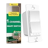
- Consistency Design: This smart wall switch (Model:RP-S01) belongs to the RP series, which is a rocker paddle appearance. It includes switch, dimmer, fan control; single pole or 3-way; neutral or non-neutral. They will be consistent all through your house.
- Tasmota Pre-flashed: This wifi light switch has a ESP32 2.4G (NOT 5G) wifi chip flashed tasmota in the factory, thus you do not need to open the casing and flash by yourself. With tasmota, you can fully control the device and keep all data locally without data security issues.
- Matter Smart Home Gadgets: smart switches can link with different platforms by scanning the smart switch matter QR code. It can become a homekit smart switch, smart switch google home, alexa smart switch in 2 min. Note: matter is a developing protocol and some hubs may have compatibility issue on matter switch. Energy Monitor is not available via Matter now. But tasmota team will also upgrade the firmware for more abilities.
- Energy Monitor: Home Assistant is recommended to review the engery monitoring data and control the switch. You can use MQTT to integrate this smart home devices into your Home Assistant Platform.
- Installation: Neutral wire is required for this wifi switch and it is single pole (NOT 3 way smart switch). Basic electrical knowledge and skills are helpful. 100-240V, 15A(Max), 50/60Hz, Fit standard switch plate (1-Gang, 2-gang, etc.), ON/OFF relay smart switches for lights(not smart dimmer switch)
Calibrate for the room
- Leave the output on an LED during setup. Open Serial Monitor at 115200 baud.
- Keep quiet while the sketch measures its startup baseline.
- Try clapping from the distance and direction where the sensor will be used.
- If speech or background noise triggers events, raise
MIN_PEAK_ABOVE_BASELINE. If claps are missed, lower it gradually. - Adjust sensor placement before making the threshold extremely sensitive. An enclosure can muffle sound or resonate.
- Test single claps, paired claps at different intervals, speech, a knock, a closing door, music, and the room’s usual fan or HVAC noise.
The gap values in the sketch define this particular interaction: the second event must occur at least 120 ms and no more than 700 ms after the first accepted event. Change them to suit the users and environment. A single clap can produce several waveform peaks; the holdoff and minimum-gap checks help suppress repeats, but this basic detector cannot guarantee that every detected event is a clap.
Crashes, No Sound, or Screen Glitches?
Random freezes, missing sound and display glitches usually trace back to one bad driver. Find and replace yours safely.Free scan · under a minuteWindows Errors? Fix Them Before They Spread
Repair common Windows errors and clear accumulated junk for a smoother, more stable PC - no reinstall needed.Free scan · no reinstallOptional: simpler digital-output demonstration
The sensor’s comparator output is easier to read, but less selective: any sound above its threshold may activate it. Use this only after checking the module’s logic polarity and ensuring its output is safe for the ESP32. Turn the module’s potentiometer to set a threshold, and change SOUND_ACTIVE_HIGH if the module signals detection with LOW.
Best Value
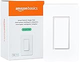
- SMART UPGRADE: Transform your home by upgrading to a smart switch that works seamlessly with Alexa, providing convenient voice control for an enhanced living experience
- GUIDED INSTALLATION: Enjoy a guided installation with our step-by-step video and user manual, providing necessary support for a smooth setup process of your smart switches for lights
- FLEXIBLE SCHEDULING: Take control of your home lighting by scheduling lights to turn on and off using Alexa routines, providing flexibility and convenience with your wifi light switch even when you're away
- VOICE-ACTIVATED CONTROL: The smart wall switch helps you effortlessly control your lighting system with voice commands via Alexa
- NO HUB REQUIRED: Simplify your setup with a smart switch that works exclusivly with Alexa, eliminating the need for additional smart home hubs or complex configurations
#include <Arduino.h>

const int SOUND_PIN = 27;
const int OUTPUT_PIN = 26;
const bool SOUND_ACTIVE_HIGH = true;
const bool OUTPUT_ACTIVE_HIGH = true;

bool lightState = false;
unsigned long lastTrigger = 0;
const unsigned long DEBOUNCE_MS = 350;

void setLight(bool state) {
  lightState = state;
  bool level = OUTPUT_ACTIVE_HIGH ? state : !state;
  digitalWrite(OUTPUT_PIN, level ? HIGH : LOW);
}

void setup() {
  Serial.begin(115200);
  pinMode(SOUND_PIN, INPUT);
  pinMode(OUTPUT_PIN, OUTPUT);
  setLight(false);
}

void loop() {
  int raw = digitalRead(SOUND_PIN);
  bool detected = SOUND_ACTIVE_HIGH ? raw == HIGH : raw == LOW;
  unsigned long now = millis();

  if (detected && now - lastTrigger >= DEBOUNCE_MS) {
    setLight(!lightState);
    lastTrigger = now;
    Serial.println(lightState ? "Light ON" : "Light OFF");
  }
}
If this version triggers continuously, the module may be set too sensitively, the assumed polarity may be wrong, or the wiring and supply may not match that board. A debounce interval prevents rapid toggles but does not make the sensor recognize a clap.
Adding a relay: keep control and load safety separate
Once the LED behaves as expected, GPIO26 can control a suitable relay-module input or a driver circuit for a low-voltage load. Check the module’s coil and logic supply requirements, input polarity, current demand, and whether a common low-voltage ground is required. Many modules are active-low, so set OUTPUT_ACTIVE_HIGH accordingly. A relay that clicks but resets the ESP32 may be drawing too much from the board’s supply or introducing electrical noise; use a properly rated separate supply and a suitable driver rather than asking a GPIO or weak USB supply to power a coil.
Do not infer mains suitability from a relay’s printed current rating alone. Load type, insulation, spacing, enclosure, wiring, regional requirements, and installation all matter. For a permanent household light, use an appropriately certified, enclosed switching product installed according to local rules by a qualified person. Never place exposed mains terminals on a solderless breadboard. Keep mains wiring out of this hobby prototype.
Do these 3 things before closing this tab:
1Scan for outdated or missing drivers - takes under a minute2Clear out junk files and repair common Windows errors3Fix the driver behind crashes, sound loss and screen glitchesTroubleshooting
| Symptom | What to check |
|---|---|
| It triggers without clapping | Raise the threshold; move the microphone away from fans, speakers, relay, and power wiring; check for enclosure resonance; lengthen the event lockout or use a better microphone. Other sharp sounds can still trigger it. |
| It misses claps | Lower the threshold gradually, check sensor power and analog wiring, aim the microphone toward the user, shorten the distance, and ensure the enclosure does not block sound. |
| One clap toggles more than once | Increase the peak holdoff or minimum interval, and verify that repeated waveform peaks are not being counted as separate events. A two-event timing rule reduces but does not eliminate this risk. |
| The relay does not activate | Confirm the actual GPIO is available on your board, the module’s input polarity, logic level, separate supply needs, and ground-reference requirements. Test the code with an LED first. |
| The ESP32 resets when the relay switches | Suspect supply sag, coil current, inductive noise, or poor wiring. Separate the relay supply as appropriate, use the correct driver and flyback protection for a bare coil, and keep microphone and switching wiring apart. |
| Analog readings fail after enabling Wi-Fi | On the original ESP32, use an appropriate ADC1 pin rather than casually moving the sensor to ADC2. Confirm the pin and ADC capabilities for other ESP32 variants. Espressif documents the original ESP32 ADC constraints. |
When a clap switch is the wrong tool
If the goal is dependable everyday lighting, a physical button, certified smart plug or switch, or smart bulb is generally a better fit than a sound threshold circuit. A PIR or mmWave sensor may suit automatic presence-based lighting; a voice assistant suits spoken commands but can depend on a network and service ecosystem. A local ESP32 prototype keeps detection local, but still needs a safe, properly designed switching solution. Do not assume clap control saves energy: that depends on whether it reliably turns lights off and how people use it.
Useful next improvements for an educational build include a physical override button, status LED, adjustable timing window, better microphone front end, or local web control. Each adds complexity; none replaces safe enclosure and switching design for household power.
Quick Recap
Product prices and availability are accurate as of the date/time indicated and are subject to change. Any price and availability information displayed on Amazon at the time of purchase will apply.


Leave a Reply