Some links on this page are affiliate links: if you buy through them we may earn a commission, at no extra cost to you.
Build a compact pixel display with a 5 V WS2812B matrix, an ESP32 running WLED, and a 3D-printed case. For a first build, an 8×8 or 8×16 panel and a regulated wall supply keep wiring and power demands manageable. Size the supply and conductors for the panel’s potential current, connect the controller and LEDs to a common ground, and start with WLED brightness limited.
What this project builds
This is a small Wi-Fi-controlled pixel display, not just a decorative lamp. Individually addressable LEDs can show pixel art, scrolling text, clocks, notifications, ambient effects, or music-reactive patterns. The finished unit has three parts:
- Pixels: a 5 V WS2812B-compatible LED matrix.
- Controller: an ESP32 development board with Wi-Fi, running WLED.
- Housing: a printed carrier and electronics tray, with a diffuser or pixel grid behind a front bezel.
WLED supports ESP32 and ESP8266 controllers and WS2812-family LEDs; its documentation favors ESP32 for new installations. See WLED’s project page and getting-started guidance.
Outdated Drivers Are Slowing You Down
One free scan finds every outdated or missing driver and matches the right update for your exact hardware.Free scan · exact hardware matchWindows Errors? Fix Them Before They Spread
Repair common Windows errors and clear accumulated junk for a smoother, more stable PC - no reinstall needed.Free scan · no reinstallChoose a matrix size
| Matrix | Pixels | Approximate full-white planning current | Good for |
|---|---|---|---|
| 8×8 | 64 | 3.84 A | Icons and first experiments |
| 8×16 | 128 | 7.68 A | Scrolling text and compact animations |
| 16×16 | 256 | 15.36 A | Pixel art and larger visual effects |
These current figures use the common worst-case planning estimate of about 60 mA per pixel at full-brightness white; they are not a prediction of typical animation use or a guaranteed measurement for every LED product. Actual draw varies by LED design, color, and brightness. The estimate and power guidance are described in Adafruit’s basic connections and powering NeoPixels guides.
#1 Best Overall

- Alloy-Wired LED Solution: Premium Performance, Budget-Friendly Value.Cost-effective solution using alloy wiring instead of premium gold wires, significantly reducing production costs while maintaining reliable performance. Perfect for entry-level projects and budget-conscious makers, delivering excellent value while expanding affordable options for LED enthusiasts.
- 2 pack 8X32 256Pixels. This 8x32 LED matrix (256 total pixels, with 32 horizontal pixels and 8 vertical pixels) features a compact 8cm (Width) x 32cm (length) [3.15in x 12.59in] square design with individually addressable smart LEDs, enabling full customization of scrolling text, pixel art, and dynamic lighting patterns for creative displays.
- Featuring wide compatibility, this LED matrix seamlessly works with Arduino, Raspberry Pi, FastLED library, Rainbowduino,K-1000C,SP802E, SP530E and WLED controllers, offering diverse effects including spectrum music visualization, scrolling text, image/video display, fireworks animations, and dynamic chase patterns depending on your controller selection
- With a chainable and flexible construction, these LED panels easily connect via 3-pin JST connectors for modular expansion. The bendable FPCB substrate conforms naturally to curved surfaces while preserving pixel integrity, perfect for creating expansive displays or organic architectural lighting installations.
- Designed for budget-conscious creators, these durable and aesthetically pleasing LED panels deliver performance rivaling premium alternatives. Perfect for DIY LED screens, advertising displays, and decorative installations in hospitality venues like hotels, KTVs, and bars, they're equally suited for indoor signage and special event decorations including Christmas and wedding celebrations.
Use this calculation to plan the supply:
maximum current ≈ pixel count × 0.06 A
maximum power ≈ maximum current × 5 V
An 8×8 or 8×16 panel is a sensible starting point. A 16×16 panel calls for more careful power distribution, multiple feed points, suitable wiring and connectors, and a larger supply.
Gather the parts
Electronics
- ESP32 development board with a WLED-supported target and accessible USB connection.
- 5 V WS2812B-compatible matrix, or addressable strip arranged as a matrix.
- Regulated 5 V supply sized for the intended load.
- 300–500 Ω resistor for the data line.
- 500–1000 µF electrolytic capacitor rated for at least 6.3 V.
- Fuse or fused power input for a larger build; a power switch and appropriately rated connector.
- Power wire selected for the current and run length; 18–20 AWG is a starting point for modest desktop builds, not a substitute for checking the actual load. Use thinner wire only for signal connections.
- Heat-shrink tubing and suitable terminals or soldered joints.
- Optional 74AHCT125, 74HCT245, or another level shifter documented for fast 3.3 V-to-5 V logic.
- Optional buttons, encoder, microphone, sensor, or status LED.
Adafruit recommends a 300–500 Ω series resistor near the first pixel and a 500–1000 µF capacitor across the LED supply rails; see its powering guide and best-practices guide.
Mechanical parts and tools
- Printed rear electronics tray, LED carrier, front bezel, and removable rear cover.
- Diffuser sheet or printed diffuser; an optional baffle grid separates pixels.
- Screws or heat-set inserts, standoffs, rubber feet, and cable strain relief.
- Black filament for the enclosure and white or translucent material for a printed diffuser.
- Soldering iron, wire cutters, multimeter, and a computer for flashing and configuring WLED.
Plan the power and wiring
Examples based on the full-white planning estimate: a 64-pixel panel reaches about 3.84 A, so a quality 5 V, 4–5 A supply provides headroom for that design target; 128 pixels reach about 7.68 A, suggesting roughly 5 V, 8–10 A when full-load capability is required; 256 pixels reach about 15.36 A and need a suitable high-current supply with multiple feed points. These are design examples, not assurances about a particular panel or supply.
Recommended Free Tools
- Feed the LEDs directly from the regulated 5 V supply. Do not route a medium or large matrix’s load through the ESP32 board’s 5 V pin or a small USB adapter.
- Power the ESP32 through a supported input on the specific development board. Board input arrangements differ.
- For larger panels, inject 5 V and ground at additional points, such as the far end, using conductors and connectors rated for the load. Keep all grounds common.
- Use a fuse appropriate to the wiring and expected load. Firmware limits do not protect undersized wires or connectors.
- In WLED, set a current limit that fits the supply and wiring, then begin testing at roughly 20–40% brightness. Increase only after checking voltage drop and heat.
Use this wiring layout. Put the resistor close to the first pixel and the capacitor close to the LED power input:
Rank #2

- Alloy-Wired LED Solution: Premium Performance, Budget-Friendly Value.Cost-effective solution using alloy wiring instead of premium gold wires, significantly reducing production costs while maintaining reliable performance. Perfect for entry-level projects and budget-conscious makers, delivering excellent value while expanding affordable options for LED enthusiasts.
- This 16x16 LED matrix (256 total pixels, with 16 horizontal pixels and 16 vertical pixels) features a compact 16cm (Width) x 16cm (length) [6.3in x 6.3in] square design with individually addressable smart LEDs, enabling full customization of scrolling text, pixel art, and dynamic lighting patterns for creative displays.
- Featuring wide compatibility, this LED matrix seamlessly works with Arduino, Raspberry Pi, FastLED library, Rainbowduino,K-1000C,SP802E, SP530E and WLED controllers, offering diverse effects including spectrum music visualization, scrolling text, image/video display, fireworks animations, and dynamic chase patterns depending on your controller selection
- With a chainable and flexible construction, these LED panels easily connect via 3-pin JST connectors for modular expansion. The bendable FPCB substrate conforms naturally to curved surfaces while preserving pixel integrity, perfect for creating expansive displays or organic architectural lighting installations.
- Designed for budget-conscious creators, these durable and aesthetically pleasing LED panels deliver performance rivaling premium alternatives. Perfect for DIY LED screens, advertising displays, and decorative installations in hospitality venues like hotels, KTVs, and bars, they're equally suited for indoor signage and special event decorations including Christmas and wedding celebrations.
5 V supply +  ─────────────────────► matrix +5 V
5 V supply –  ───────┬─────────────► matrix GND
                     └─────────────► ESP32 GND

ESP32 GPIO ─► 300–500 Ω resistor ──► matrix DIN

ESP32 power input ◄───────────────── regulated 5 V

For additional power injection:
5 V supply +  ─────────────────────► additional matrix +5 V feed
5 V supply –  ─────────────────────► additional matrix GND feed
Connect the controller ground to LED ground; connect data to DIN, not DOUT, and follow the direction arrows on the panel. Never connect a 5 V matrix to a 12 V or 24 V supply. Avoid relying on thin jumper wires or an ordinary USB cable for high-current LED power. Adafruit’s connection guidance also recommends establishing ground before other connections and disconnecting it last.
Do you need a level shifter?
ESP32 GPIO uses 3.3 V logic, while the LEDs are powered at 5 V. A short data wire may work directly, but whether it does depends on the LED’s input threshold, supply voltage, noise, and wiring. Direct connection is not guaranteed across WS2812-compatible products. For a finished build, a longer data run, or a noisy setup, use a suitable 5 V logic level shifter. Adafruit discusses this variation in its NeoPixel Uberguide.
Choose a GPIO for the actual board
Do not assume every ESP32 GPIO is interchangeable. Pin availability and boot-related behavior depend on the development board and chip variant. Pick a documented output pin from the exact board’s pinout, avoid sensitive pins unless you understand their behavior, and enter the same pin in WLED. Espressif’s ESP32 datasheet documents chip GPIO functions; the board’s own pinout determines what is exposed and how it is used.
The Tool Desk
Outbyte Driver Updater FREEScan for outdated or missing drivers - takes under a minuteDriver Scan →Outbyte PC Repair FREEClear out junk files and repair common Windows errorsFree Scan →Design the printed case around the panel
Measure the purchased matrix rather than designing from a listing’s nominal dimensions. Record its width, height, PCB thickness, mounting holes, LED pitch, connector and solder-pad locations, cable exit direction, and the space needed for the ESP32, capacitor, level shifter, switch, and power connector.
Rank #3

- Alloy-Wired LED Solution: Premium Performance, Budget-Friendly Value.Cost-effective solution using alloy wiring instead of premium gold wires, significantly reducing production costs while maintaining reliable performance. Perfect for entry-level projects and budget-conscious makers, delivering excellent value while expanding affordable options for LED enthusiasts.
- 2 pack 16X16 256Pixels. This 16x16 LED matrix (256 total pixels, with 16 horizontal pixels and 16 vertical pixels) features a compact 16cm (Width) x 16cm (length) [6.3in x 6.3in] square design with individually addressable smart LEDs, enabling full customization of scrolling text, pixel art, and dynamic lighting patterns for creative displays.
- Featuring wide compatibility, this LED matrix seamlessly works with Arduino, Raspberry Pi, FastLED library, Rainbowduino,K-1000C,SP802E, SP530E and WLED controllers, offering diverse effects including spectrum music visualization, scrolling text, image/video display, fireworks animations, and dynamic chase patterns depending on your controller selection
- With a chainable and flexible construction, these LED panels easily connect via 3-pin JST connectors for modular expansion. The bendable FPCB substrate conforms naturally to curved surfaces while preserving pixel integrity, perfect for creating expansive displays or organic architectural lighting installations.
- Designed for budget-conscious creators, these durable and aesthetically pleasing LED panels deliver performance rivaling premium alternatives. Perfect for DIY LED screens, advertising displays, and decorative installations in hospitality venues like hotels, KTVs, and bars, they're equally suited for indoor signage and special event decorations including Christmas and wedding celebrations.
Useful first-print starting points are 1–2 mm clearance around the matrix, 18–30 mm of internal depth for a small box, 5–15 mm between LEDs and diffuser, and 2–3 mm enclosure walls. Treat these as adjustable starting dimensions: panels and components vary by supplier.
Use separate, serviceable parts
- Rear electronics tray: hold the controller and power connections, with ventilation near electronics and power entry.
- LED carrier: locate the panel without permanently trapping it.
- Spacer or grid: set diffuser distance or separate pixels to reduce light bleed.
- Front bezel: retain a removable diffuser.
- Rear cover: allow access to USB, reset or boot controls, fuse, and power disconnect.
Add strain relief for incoming cables, mounting points for fasteners, and clearance around components. A design that allows panel replacement is easier to repair than a sealed one.
Choose a front treatment
- White translucent sheet: generally gives a smooth-looking glow.
- Printed translucent panel: convenient to make, but print layers may remain visible.
- Printed grid or baffle: gives more distinct pixels and reduces light bleed, at the cost of more depth and print complexity.
- No diffuser: brightest, but can look harsh and uneven.
Do not assume a printed diffuser will be optically uniform. LED spacing, material, print orientation, layer lines, and diffuser gap all affect the result. Print a small test section first. Use PLA only for ordinary indoor conditions where its heat limitations are acceptable; do not place it around a hot supply or in direct sun without assessing the temperature.
Flash WLED and connect the controller
WLED’s normal browser-installer flow is straightforward when the installer is available: connect the board by USB, flash the suitable build, join its setup access point if one appears, enter Wi-Fi credentials, and open the device’s assigned IP address. Use a data-capable USB cable; a charge-only cable will not expose a serial device. The installer page identifies missing CP2102 or CH34x drivers as common detection issues: WLED installer.
Rank #4
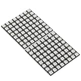
- Product Dimensions: This 8x8 LED matrix (64 pixels total, 8 pixels horizontally and 8 pixels vertically) features a compact 6.5x6.5cm square design for creative display effects.
- Reliable Materials: Made of ABS and copper with alloy wire, this led matrix maintains reliable performance, making it ideal for your DIY projects.
- Practical Design: Each LED on the led matrix panel can be cut off, and the remaining strip will still function normally. You can freely shorten, lengthen, or bend the strip as needed.
- Wide Compatibility: Works seamlessly with most controllers on the market and offers a variety of effects depending on your controller choice, including spectrum music visualization and dynamic modes.
- Cost-Effective: Individually addressable ws2812b led strip are good for entry-level projects and makers on a budget, providing excellent value while offering an affordable option for LED enthusiasts.
Installer status is time-sensitive: on August 18, 2026, the official installer page reported temporary maintenance and directed users to an alternate installer or WLED binary releases. Check the page when you build; if the web installer remains unavailable, follow the current alternate flashing route linked there rather than using an unverified binary or an outdated set of flashing steps.
- Connect the ESP32 to a computer using a known data-capable USB cable.
- Use the official WLED installer if operational, select the serial port for the board, and install the appropriate build. If the port is absent, check the USB cable and the board’s CP2102 or CH34x driver.
- Reboot the board and join its temporary WLED access point if it appears.
- Enter the home Wi-Fi credentials and find the device’s assigned IP address.
- Open that address in a browser to configure the LEDs.
Configure the matrix in WLED
In LED configuration, set the LED type to WS281x/WS2812-compatible, enter the actual pixel count, choose the GPIO connected to DIN, and select the color order. GRB is common but not universal, so test rather than assume. Set the current limit to suit the supply and wiring and begin with a conservative brightness cap.
For a 2D matrix, enter its width and height, then select the wiring layout: serpentine or progressive, horizontal or vertical, and any reversed direction or panel arrangement required. A pure red, green, blue, and white test followed by a moving chase will expose most color-order, direction, and mapping errors.
Quick wins for a faster PC:
Fix the driver behind crashes, sound loss and screen glitchesFind Drivers →Repair Windows errors before they cause bigger problemsFix Now →Scan for outdated or missing drivers - takes under a minuteDriver Scan →Bench-test before fitting the enclosure
- With power disconnected, inspect polarity and solder joints. Measure the supply output and confirm it is regulated 5 V.
- Connect ground, then the LED power and data connections. Check that ESP32 and matrix grounds are common, the data resistor is in place, and the wire reaches DIN.
- Power the controller and matrix at low brightness. Test solid red, green, blue, and white.
- Run a moving chase to confirm data direction and the panel’s row order; verify that the farthest pixels do not dim or shift color.
- Check wires, terminals, and connectors for heat. Run the box for 10–15 minutes at normal brightness before enclosing it.
If a multimeter reading shows the 5 V rail sagging under load, reduce brightness and inspect the supply, wiring, connectors, and injection points before continuing.
Best Value

- Alloy-Wired LED Solution: Premium Performance, Budget-Friendly Value.Cost-effective solution using alloy wiring instead of premium gold wires, significantly reducing production costs while maintaining reliable performance. Perfect for entry-level projects and budget-conscious makers, delivering excellent value while expanding affordable options for LED enthusiasts.
- This 8x32 LED matrix (256 total pixels, with 32 horizontal pixels and 8 vertical pixels) features a compact 8cm (Width) x 32cm (length) [3.15in x 12.59in] square design with individually addressable smart LEDs, enabling full customization of scrolling text, pixel art, and dynamic lighting patterns for creative displays.
- Featuring wide compatibility, this LED matrix seamlessly works with Arduino, Raspberry Pi, FastLED library, Rainbowduino,K-1000C,SP802E, SP530E and WLED controllers, offering diverse effects including spectrum music visualization, scrolling text, image/video display, fireworks animations, and dynamic chase patterns depending on your controller selection
- With a chainable and flexible construction, these LED panels easily connect via 3-pin JST connectors for modular expansion. The bendable FPCB substrate conforms naturally to curved surfaces while preserving pixel integrity, perfect for creating expansive displays or organic architectural lighting installations.
- Designed for budget-conscious creators, these durable and aesthetically pleasing LED panels deliver performance rivaling premium alternatives. Perfect for DIY LED screens, advertising displays, and decorative installations in hospitality venues like hotels, KTVs, and bars, they're equally suited for indoor signage and special event decorations including Christmas and wedding celebrations.
Assemble the display
- Secure the matrix to its carrier without stressing the PCB or solder pads.
- Mount the ESP32 and route power and data wires so they cannot be pinched by the rear cover.
- Fit strain relief, the switch, and any fuse where they remain accessible.
- Install the grid or diffuser spacer, then retain the diffuser with a removable bezel.
- Close the case while preserving USB and reset access, then run the normal-brightness test again and check for excess heat.
Choose panels, firmware, and visual style
Preassembled panel or strip-built matrix
| Option | Best fit | Trade-off |
|---|---|---|
| Preassembled panel | Beginners who want consistent spacing and faster assembly | Fixed dimensions, wiring direction, and connector location |
| Strip-built matrix | Custom dimensions, unusual shapes, or flexible layouts | More solder joints, alignment work, row-order errors, and demanding power distribution |
WLED or custom firmware
| Route | Best fit | Trade-off |
|---|---|---|
| WLED | Fast setup, browser or phone control, presets, effects, and Wi-Fi operation | Behavior depends on the installed build and its available settings |
| Custom Arduino IDE or PlatformIO firmware with a suitable LED library | Specialized buttons, sensors, animations, or battery optimization | You must maintain the code, board settings, library versions, and update path |
The original example project uses an ESP8266-style approach with custom firmware, but its sketch and pin assignments should not be assumed to match an ESP32 build. See the project at Hackster.
ESP32 or ESP8266
Choose ESP32 for a new build with more room for larger matrices, 2D mapping, and later expansion. An ESP8266 remains reasonable for a small panel, an existing design, or hardware already on hand; WLED continues to support it, but it offers less headroom.
Battery power is a separate, advanced design
Use a regulated wall supply for the first build. The cited Hackster project includes a battery and TP4056 module while discussing a 2S or 3S pack; treat that as project inspiration, not a validated charging design. A TP4056 single-cell charger is not a charger for a series-connected 2S or 3S pack. See the project description at Hackster.
Do these 3 things before closing this tab:
1Fix the driver behind crashes, sound loss and screen glitches2Repair Windows errors before they cause bigger problems3Scan for outdated or missing drivers - takes under a minute- Lower-complexity portable approach: use a single protected 3.7 V lithium cell, a charger/protection board intended for one cell, and a 5 V boost converter sized for the LED load, with a fuse and switch. Confirm whether the ESP32 needs its own regulated input.
- Higher-power approach: use a correctly configured 2S or 3S pack with a matching balance charger, suitable BMS, 5 V buck converter, fuse, cell restraint, and ventilation.
Do not connect a battery pack until its cells, charger, protection, wiring, and converter are designed for the chosen configuration and current.
Troubleshoot by symptom
Nothing lights
- Disconnect power; check the 5 V supply at the matrix input and verify polarity.
- Confirm ESP32 ground and matrix ground are connected, and that the data wire reaches DIN rather than DOUT.
- Check the panel connector pinout, WLED GPIO setting, USB data cable, and whether flashing completed.
- Follow the panel’s direction arrows and test one panel or segment before reconnecting the full display.
Flicker or random colors
- Reduce brightness and check for voltage drop, loose solder joints, or a poor common ground.
- Shorten and improve the data-wire route; verify the series resistor near the first LED and capacitor across the LED input rails.
- Add power injection where needed. If the 3.3 V signal is marginal, add a suitable level shifter.
Only the first LED or row works
- Check for a broken pixel or data trace and confirm that each row’s output connects to the next row’s input.
- Verify physical arrows and correct the 2D serpentine, progressive, or orientation setting in WLED before rewiring.
Colors are swapped
Display pure red, green, and blue, then change the color-order setting (for example, GRB, RGB, or BGR) until each test appears correctly.
Quick Recap
The ESP32 resets, pixels dim, or wiring gets hot
- Do not draw the matrix load through the development board or USB port. Use the dedicated 5 V supply and a supported ESP32 input.
- Lower WLED’s current limit and brightness, then measure the 5 V rail during a bright test.
- Check the supply rating, wire gauge, connector rating, grounding, and power injection. Stop using the unit if wiring or connectors become hot.
- If the enclosure heats up, add ventilation and space, reduce brightness, and replace an inadequate supply or wiring before resuming.
Product prices and availability are accurate as of the date/time indicated and are subject to change. Any price and availability information displayed on Amazon at the time of purchase will apply.


Leave a Reply