The Tool Desk
Outbyte Driver Updater FREEFix the driver behind crashes, sound loss and screen glitchesFind Drivers →Outbyte PC Repair FREEClear out junk files and repair common Windows errorsFree Scan →Some links on this page are affiliate links: if you buy through them we may earn a commission, at no extra cost to you.
Yes: an nRF52840 can form the core of a battery-powered Zigbee gate sensor. Use a reed switch or suitably low-current Hall sensor as a GPIO input, implement the device as a Zigbee Sleepy End Device (SED), and measure the finished circuit before estimating battery life. Nordic’s current Zigbee development path for the nRF52840 is its Zigbee R23 add-on for nRF Connect SDK; the older R22 add-on is in maintenance mode and is not recommended for new designs.
The system is a contact and magnet, an nRF52840 waking on a GPIO transition, and a powered Zigbee parent that forwards reports to a coordinator and home-automation system. This is a monitoring project, not a certified alarm, safety interlock, or access-control system.
What the sensor detects—and what it cannot
Mount a magnet on the moving gate and a reed switch or Hall sensor on the fixed post. When the magnet is close enough to activate the sensor, the firmware maps that input to a defined state such as closed; when the magnet moves away, it reports open. Decide and document the polarity during installation rather than assuming that an electrically closed contact always means the gate is closed.
Quick wins for a faster PC:
Fix the driver behind crashes, sound loss and screen glitchesFind Drivers →Repair Windows errors before they cause bigger problemsFix Now →A binary contact reports magnet proximity, not whether a latch has engaged or whether the gate is fully secured. If the gate can rest partly open, consider a second sensor or a mechanically positioned sensor that distinguishes the position that matters. Tamper, battery, temperature, and periodic last-seen reports are optional additions, not substitutes for a dependable gate-position installation.
#1 Best Overall
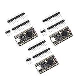
- The NRF5280 development board has a 3.7V lithium battery interface and a software switch that can cut off the power of the LED. When turned off, the standby power consumption can reach 1mA.
- NRF52840 is a high-performance, low-power wireless SoC chip launched
- The NRF52840 chip uses an ARM Cortex-M4F processor, clocked at 64MHz, with built-in 1MB of flash memory and 256KB of RAM
- It also has a variety of peripherals, including ADC, PWM, SPI, I2C, UART, USB and GPIO, etc.
- NRF52840 also supports a variety of security functions, such as AES encryption, SHA-256 hashing and True Random Number Generator (TRNG)
Choose the sensing hardware
Reed switch: simplest low-power option
A reed switch can connect a GPIO to ground when activated, with the GPIO held high by an internal or external pull-up. It uses essentially no sensor standby current in a static state, but the glass body can be damaged by vibration, contacts can bounce or wear, and magnet alignment and distance determine switching behavior. Protect it mechanically and test the actual gate travel.
Hall-effect sensor: contactless, but check its current
A Hall sensor avoids mechanical contacts and can be a better fit where vibration or wear is a concern. Its threshold, polarity, temperature behavior, and standby current depend on the specific part. A continuously powered Hall sensor can consume more than the sleeping MCU; use an ultra-low-standby-current part or switch its supply if the design supports that safely.
For either sensor, use firmware debounce: wake on a transition, wait for the measured contact behavior to settle, re-read the input, and suppress duplicate reports. A remote switch cable should be treated as an exposed electrical path, not as a harmless short wire. Keep it short where possible, use twisted conductors and a weatherproof connector, and consider series resistance and ESD protection. Define what a broken wire means in the application.
Do these 3 things before closing this tab:
1Repair Windows errors before they cause bigger problems2Fix the driver behind crashes, sound loss and screen glitches3Clear out junk files and repair common Windows errorsPrototype first, then build for deployment
Prototype with the nRF52840 DK
The nRF52840 DK is a practical platform for validating firmware, GPIO behavior, commissioning, and radio reports. It also works with Nordic’s Power Profiler Kit II for current measurement. It is a development board, not a representative low-power finished sensor: USB, debug circuitry, regulators, LEDs, and other board loads can dominate sleep current.
Design the deployable board around the complete power path
A final design can use an nRF52840 module or a custom PCB. Account for the antenna and RF layout, the clocks required by the chosen design, battery input and regulation, programming and recovery access, a protected sensor input, and any optional battery measurement or status LED. Include a reset or pairing control that cannot be triggered accidentally by gate movement.
The nRF52840 product brief specifies a 1.7–5.5 V supply range for the SoC, but that does not establish the safe input range for a particular module, regulator, GPIO, or board. Check the complete power path and battery chemistry before connecting a cell directly. The device has 1 MB flash and 256 KB RAM, and supports IEEE 802.15.4 at 250 kbps; these are silicon capabilities, not guarantees that a particular board or firmware image is suitable.
Rank #2

- NRF52840 is a high-performance, low-power;Development Board Compatible With Nice Nano V2.0 Charging Management Pro Micro NRF52840
- It is designed for versatile applications in electronic module development, making it ideal for both hobbyists and professional projects
- The NRF52840 Development Board is a high-performance integrated circuit compatible with Nice!Nano V2.0, featuring Bluetooth and charging management capabilities
- he NRF5280 development board has a 3.7V lithium battery interface and a software switch that can cut off the power of the LED. When turned off, the standby power consumption can reach 1mA
- The NRF52840 chip uses an ARM Cortex-M4F processor, clocked at 64MHz, with built-in 1MB of flash memory and 256KB of RAM
For a reed-switch prototype, a common circuit is GPIO with pull-up and switch to ground. Choose the input mapping to match magnet placement, and ensure the input has a defined state if the wire is disconnected. Avoid a large filter capacitor that delays a gate transition unless measurements justify it; debounce in firmware first.
Plan the battery without guessing
Battery choice is a trade-off between size, pulse delivery, service interval, and temperature. A coin cell is compact but can have limited pulse capability and reduced cold-weather performance. AA cells occupy more space but are generally a more forgiving source for radio bursts. Lithium primary cells can offer good shelf life, but verify pulse behavior and regulator compatibility. Rechargeable lithium-ion or LiFePO₄ requires a suitable charging and protection design and a temperature plan for an unattended outdoor installation.
Nordic’s nRF52840 product brief lists approximately 0.4 µA System OFF current with no RAM retention and 1.86 µA with full RAM retention under specified conditions. These are chip operating points, not the average current of a Zigbee sensor: radio activity, parent polls, the board, regulator, sensor, pull-ups, battery monitor, LEDs, retries, and leakage all affect the real result.
A first-order estimate is:
Estimated hours = usable battery capacity (mAh) ÷ average complete-device current (mA).
Use measured average current from the assembled design and a defensible usable-capacity figure for the selected battery, load, and temperature. The result is an estimate, not a runtime guarantee. Include margin for cold, battery aging, radio retries, regulator losses, and more gate activity than expected. If the sensor’s current waveform has not been measured, a multi-year battery claim is not established.
What’s actually slowing this PC down?
Pick the symptom - the matching free tool is one click away.
Use a Sleepy End Device role
A battery gate sensor is normally a Zigbee Sleepy End Device, not a router. It sleeps with its receiver off between scheduled polls, wakes locally when the GPIO changes, sends the state, and returns to sleep when the stack has finished its work. It must join through a powered coordinator or router parent that can buffer traffic while the sensor sleeps.
Rank #3

- Maximum performance: the Pro micro microcontroller development board runs at 5 V/16 MHz and supported by IDE V1.0.1 for smooth programming. Suitable for Arduino.
- The NRF52840 chip uses an ARM Cortex-M4F processor, clocked at 64MHz, with built-in 1MB of flash memory and 256KB of RAM
- The NRF5280 development board has a 3.7V lithium battery interface and a software switch that can cut off the power of the LED. When turned off, the standby power consumption can reach 1mA
- SuperMini NRF52840 is a Pro Micro alternative development board that is compatible with Nice! for Nano. Its pins are the same as ProMicro, which means it can be used with almost any Pro Micro keyboard.
- Pro Micro with Atmega32U4 chip Development Board,Pro Micro 5V/16MHz Nano microcontroller Development Board with Built-in USB updater Type-C Interface Compatible with Arduino IDE
That creates two different response times. A local contact interrupt can wake the MCU promptly, while receiving a downlink command depends on the polling interval and parent behavior. This is usually a reasonable trade for a device that mainly sends gate events rather than receiving frequent commands. A battery SED cannot extend the mesh like a continuously powered router; if coverage is poor, add a powered Zigbee router nearer the gate and test the installed path.
Nordic’s SED configuration guidance documents setting zb_set_rx_on_when_idle(ZB_FALSE) before starting the ZBOSS stack, along with relevant RAM power-down options. Follow the sleep and scheduler mechanism for the exact SDK and add-on release in use. Do not invoke generic deep sleep while Zigbee transmissions, retries, timers, or polling work are still pending.
Build the Zigbee application
Start from Nordic’s current SDK path
Use Nordic’s Zigbee R23 add-on for nRF Connect SDK, which uses the ZBOSS stack and supports the nRF52840. Install the nRF Connect SDK release and matching toolchain required by the add-on documentation. Start with a current Zigbee sample, such as the R23 light-switch sample, rather than assuming instructions for an older nRF5 SDK project apply unchanged. The sample documents SED behavior and nRF52840 support.
Recommended Free Tools
For an initial DK build, the version-neutral command shape is:
west build -b nrf52840dk/nrf52840 <path-to-zigbee-application>
west flash
These commands illustrate the workflow, not a release-independent tested recipe: sample paths, board targets, configuration symbols, and flash instructions can change with the SDK and board definition. Use the target and commands specified for the exact release you install. The older R22 documentation remains useful for its SED configuration details, but Nordic marks that add-on as maintenance-mode software rather than its recommended path for new designs.
Define a standard device model
Expose a conventional contact-sensor endpoint and test its presentation on the target coordinator. Define the endpoint number, device ID, server clusters, initial attributes, reporting intervals and change thresholds, commissioning behavior, and factory-reset behavior. A door/window contact model is a common direction, but cluster and attribute choices do not guarantee identical entity discovery or battery reporting across every controller. Avoid a proprietary cluster unless the flexibility is worth potentially needing coordinator-specific configuration or a custom converter.
Rank #4

- Maximum performance: the Pro micro microcontroller development board runs at 5 V/16 MHz and supported by IDE V1.0.1 for smooth programming. Suitable for Arduino.
- The NRF52840 chip uses an ARM Cortex-M4F processor, clocked at 64MHz, with built-in 1MB of flash memory and 256KB of RAM
- The NRF5280 development board has a 3.7V lithium battery interface and a software switch that can cut off the power of the LED. When turned off, the standby power consumption can reach 1mA
- SuperMini NRF52840 is a Pro Micro alternative development board that is compatible with Nice! for Nano. Its pins are the same as ProMicro, which means it can be used with almost any Pro Micro keyboard.
- Pro Micro with Atmega32U4 chip Development Board,Pro Micro 5V/16MHz Nano microcontroller Development Board with Built-in USB updater Type-C Interface Compatible with Arduino IDE
Include only data the device can defend: contact state, optional tamper state, battery voltage or a carefully calibrated battery estimate, and optionally temperature. A voltage measurement is often more honest than a percentage when no chemistry- and load-specific discharge curve is available.
Implement the event path
- Initialize the GPIO and read the current contact state before advertising a report.
- Initialize the Zigbee endpoint and SED behavior, then start commissioning or rejoin handling.
- Configure reporting and enter the stack’s event loop and sleep flow.
- On a GPIO wake, debounce the input, re-read it, and ignore the event if the stable state has not changed.
- Update the contact attribute and request an immediate report through the stack; optionally include battery data when its reporting policy warrants it.
- Allow the stack to complete transmission and scheduled work before returning to its documented low-power state.
- Wake periodically for a heartbeat and battery report if you need an availability signal.
Gate vibration can cause several transitions from one physical movement. Tune the stability period against the actual switch and gate, suppress duplicates, and avoid a fixed debounce value that has not been checked on the installation. Configure the GPIO transition as a wake source; periodic polling alone can miss a short movement while the MCU sleeps.
Independent reader supportYour contribution helps us test, update, and keep practical guides available for everyone.Commissioning and Home Assistant integration
Provide an intentional way to enter joining mode and reset the device, such as a button-held-at-boot path. Use a short, visible LED indication for searching, joined, reporting, or error states, and keep diagnostics off during normal operation. Store network parameters using the supported stack facilities, and require deliberate confirmation for factory reset so vibration or enclosure contact cannot erase them.
Nordic’s commissioning documentation describes network steering and the differing coordinator, router, and end-device paths. For testing, Nordic documents an nRF52840 DK coordinator sample, while the light-switch sample requires a separate coordinator for network tests: see the network coordinator sample.
For Home Assistant, choose the integration and coordinator deliberately. ZHA is Home Assistant’s native Zigbee integration. Zigbee2MQTT is an alternative for users who want its MQTT-based service and converter ecosystem. Home Assistant notes there is no universal official compatibility list covering every Zigbee device, so a custom endpoint may pair but still need correct clusters, reporting configuration, or platform-specific handling to appear as expected.
Use a mainstream supported coordinator for a lower-risk home deployment rather than making an nRF52840 ZBOSS coordinator the default. Zigbee2MQTT currently labels ZBOSS-based coordinator adapters experimental, even though it lists tested nRF52840 hardware. Its ZBOSS adapter documentation describes that path. A coordinator connects the Zigbee network to Home Assistant; it is not a gate-side repeater. The Home Assistant Connect ZBT-2 is a current coordinator option, while the ZBT-1 is discontinued and replaced by it; check the ZBT-2 product page for current regional availability and details.
Validate power, radio, and outdoor installation
Measure the whole current profile
Use the Power Profiler Kit II or equivalent instrumentation on the final board to capture sleep, contact-wait, wake, transmit, commissioning, and rejoin behavior. Record battery voltage, board revision, firmware and SDK/add-on release, poll interval, radio conditions, temperature, and a stated event profile. Measure the radio burst as well as long-term average current; a battery that reads well at rest may droop enough during transmission to reset the MCU. Check regulator behavior and reset reasons, and select adequate pulse capability and local capacitance within the design limits.
Test the complete network path
- Pair with the intended coordinator and verify the endpoint and contact state.
- Open and close the gate repeatedly; confirm one correct report per stable state change.
- Test quick transitions, gate vibration, and the installed magnet alignment.
- Restart the coordinator and verify recovery without removing the battery.
- Test parent loss and rejoin behavior; use retry backoff rather than rapid, endless attempts.
- Test battery reporting and heartbeat timeout behavior in the actual integration.
- Repeat range and reporting tests with the final enclosure, orientation, and mounting location.
Protect the installation
A metal gate can attenuate or detune a 2.4-GHz antenna. Keep the antenna away from large conductive surfaces, observe the module’s keep-out guidance, and test the final mounting orientation. Use a gasketed enclosure, cable glands and strain relief where needed, corrosion-resistant contacts, and an appropriate condensation strategy; a nominally weather-resistant box does not prevent condensation. Keep battery access practical while preventing casual tampering, and consider conformal coating only where compatible with the design and service plan.
Quick Recap
Troubleshoot by symptom
| Symptom | Checks and recovery |
|---|---|
| Build fails | Confirm the SDK release, toolchain, R23 add-on, sample path, and board target match the documentation for that release; do not mix legacy sample instructions without porting their configuration. |
| Flashes but does not boot | Check board target and power input limits, GPIO and clock configuration, reset reason, and whether the application was built for the actual hardware rather than the DK. |
| Does not enter pairing mode | Check the button-held-at-boot logic, commissioning state, and coordinator permit-join window; use the firmware’s time-limited LED indication to distinguish searching from other states. |
| Pairs but does not report | Verify the endpoint, clusters, attribute update, reporting setup, and coordinator’s device presentation. Confirm the stack completes the send before its sleep path. |
| Reports repeatedly | Check magnet geometry, contact bounce, vibration, interrupt edges, stability interval, and duplicate suppression. |
| Misses quick transitions | Confirm the GPIO interrupt is configured as a wake source and test whether the contact state changes faster than the debounce or sampling logic can resolve. |
| Works on the bench but not outdoors | Check antenna placement near metal, final enclosure effects, parent/router coverage, water ingress, connector corrosion, and magnet alignment under real gate movement. |
| Resets during transmission | Measure battery voltage during the radio burst; review cell pulse capability, regulator dropout, wiring resistance, local capacitance, and reset diagnostics. |
| Battery drains quickly | Measure the complete board, including regulator, sensor, pull-ups, LEDs, and radio; inspect poll interval, retries, event duplicates, and sensor standby current. |
| Unavailable after coordinator restart | Check normal polling, parent recovery and rejoin policy, heartbeat timeout, and whether a powered router provides dependable coverage. |
| ZHA and Zigbee2MQTT show different entities | Compare endpoint and cluster exposure, reporting configuration, and platform support; protocol branding alone does not ensure identical discovery behavior. |
Product prices and availability are accurate as of the date/time indicated and are subject to change. Any price and availability information displayed on Amazon at the time of purchase will apply.


Leave a Reply