Free tools Windows power users keep installed
One-click scans. No signup required.
Some links on this page are affiliate links: if you buy through them we may earn a commission, at no extra cost to you.
Barrel connector repair depends on which part has failed. A damaged plug on a power cable is usually replaced by cutting it off and soldering on a correctly matched plug. A loose or broken jack inside a device may need a cracked solder joint reflowed, the jack replaced, or a torn PCB pad repaired. Before soldering, verify the connector’s dimensions, polarity, pin arrangement, mounting style, voltage, and current rating.
Do not assume that a connector that fits is electrically safe. A 5.5 mm outside diameter, for example, may use a 2.1 mm or 2.5 mm internal diameter. Many consumer adapters are center-positive, but polarity is not universal.
What a barrel connector is
A DC barrel connector—also called a coaxial power connector, DC plug, DC jack, or coaxial power jack—is a cylindrical connector used to deliver low-voltage power. The male plug is commonly attached to an adapter cable; the female jack is mounted in a device, enclosure, panel, or circuit board.
Quick wins for a faster PC:
Scan for outdated or missing drivers - takes under a minuteDriver Scan →Clear out junk files and repair common Windows errorsFree Scan →Fix the driver behind crashes, sound loss and screen glitchesFind Drivers →The plug and jack normally contain an outer sleeve contact and an inner pin contact. Some jacks have a third, switched contact that disconnects a battery or secondary power path when a plug is inserted. SparkFun’s connector guide explains the different contact arrangements and polarity conventions.
#1 Best Overall

- ✅Safety Tips: Maximum 5A Current 1V-24V No Heat | Heavy Duty Inner Wire leads and Connecting Portion, easily install with 16-26AWG Gauge Wire.
- ✅Easily Install: Tight Screw on Terminal | No electrical tap, No splicing, No crimping, No-Soldering Needed | Easy to Install within 3~10sec.
- ✅Universal design with Premium Quality: Double Layer (Injection Moulding) Provide Best Polarity Connection and Insulation DC Electrical Connector connects wire lead end to a DC 2.1x5.5mm port/connector/jack.
- ✅Application: For 1-24 Volt Power Supply, 2.1 x 5.5 mm Connectors, 5V 12 V 24 V CCTV Cable Connection, Led Strip Extention, DIY Board, Security Tailgat Camera, Video Balun. Best choice for LED strip lights, CCTV Camera, Audio & Video connection.
- ✅All Connectors are been packed & QC in the USA. Our business policy: 100% satisfaction guaranteed. Please contact us with any problems anytime through Amazon message. We provide 24/7 service
In a center-positive arrangement, the inner contact is positive and the outer sleeve is negative. Center-negative and unusual proprietary arrangements also exist, so never infer polarity from the connector’s appearance or wire colors.
Symptoms of a faulty connector
- The device turns off when the plug or cable is moved.
- Power cuts in and out when the cable is wiggled.
- The plug no longer stays seated.
- The jack rotates, rocks, or moves inside the enclosure.
- The power LED flickers.
- The connector has cracked plastic, bent metal, corrosion, discoloration, or a burnt smell.
- The adapter measures correctly, but voltage does not reach the circuit board.
- The jack has pulled away from the PCB or has visibly cracked solder joints.
These symptoms do not prove that the connector itself is defective. An intermittent fault may come from a broken cable conductor, cracked solder joint, lifted PCB pad, damaged trace, fuse, reverse-polarity protection circuit, or failed power-supply circuitry. Cleaning and inspection can sometimes resolve contamination-related interruptions, but cleaning cannot repair mechanical or electrical damage. Red Panda’s troubleshooting guidance also identifies movement-related power loss as a reason to inspect and clean the barrel connection.
First identify what failed
Cable-mounted male plug
The plug is the damaged part when the failure is on the adapter lead: a broken molded housing, failed strain relief, cable fatigue near the plug, bent contacts, or an internal conductor fracture. If the rest of the cable and adapter are reliable, the plug can often be replaced. If the cable is brittle or damaged in several places, replacing the complete adapter is safer.
PCB-mounted female jack
A device jack may have cracked solder joints, worn internal spring contacts, a broken housing, failed mounting tabs, detached pads, or a damaged trace. Resoldering is appropriate only when the jack and PCB are mechanically sound. A cracked or worn jack normally needs replacement.
Panel- or chassis-mounted jack
A panel jack is secured to the enclosure rather than relying only on PCB solder joints. If an exact PCB replacement is unavailable, an equivalent panel or in-line jack can sometimes be connected to the original board with short insulated wires. It must be mechanically secured so cable movement does not load the board.
Manufacturers such as Switchcraft offer PCB, panel, cable-mounted, locking, and non-locking DC connectors. These categories are not automatically interchangeable.
Safety before opening equipment
These procedures are intended for the external, low-voltage DC side of an adapter. They are not instructions for repairing mains circuitry.
PC Slower Than It Used to Be?
A free scan shows the junk files, broken settings and background clutter dragging Windows down - then fixes them in one click.Free scan · Windows 10 & 11Crashes, No Sound, or Screen Glitches?
Random freezes, missing sound and display glitches usually trace back to one bad driver. Find and replace yours safely.Free scan · under a minute- Unplug the AC adapter from the wall.
- Disconnect the DC plug from the device.
- Remove batteries where practical.
- Wait for capacitors to discharge.
- Do not work on exposed mains wiring or energized equipment unless qualified to do so.
- Never use a multimeter’s continuity mode on a powered circuit.
- Verify polarity and check for shorts before applying power.
Useful tools include a temperature-controlled soldering iron, solder, flux, desoldering braid or a solder sucker, side cutters, wire strippers, tweezers, a digital multimeter, magnification, bright lighting, heat-shrink tubing, and isopropyl alcohol or suitable electronics contact cleaner. Large ground-connected terminals may need a broader tip to transfer heat effectively; avoid overheating the board.
Rank #2
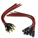
- Real Thick 18 AWG - Real 18 AWG vs Common 22 AWG, real 18 AWG are bigger wire than other 22 AWG pigtails, as it has heavy gauge with 43 pcs 0.14 mm 100% copper strands inside one cable, total 86 pcs 0.14 mm copper strands inside the two Red / Black cables. This makes the difference when using with bigger power supplies, and allows them to be used for higher current devices, they should be good to 5A or even a touch more with real 18 AWG
- Safe and Rapid Transmission - Heavy-duty quality with 43 x 0.14 mm 100% copper strands brings the reliable, secure connection and rapid transmission. 18AWG DC Power Pigtail Cable provides a more safer DIY solution for DC power connectivity, work with a power adapter or a power supply box
- Easy Installation - Easy to weld and install, as the ends of the DC power pigtail cables are pre-tinned making them super easy to solder. Also features two wires on the other Red Black wire jackets indicate polarity. They are fairly long too, 11" total, 9.5" of wire
- Compatibility - Easy DC Power solution, compatible with all CCTV systems and other 2.1*5.5mm DC power devices like part lighting or led strips. Very versatile. This 18AWG DC Power Pigtail provide a very good reliable DC power connection
- What You Get -10 pcs Red/Black Male Pigtails DC Power Connectors, 10 pcs Red/Black Female Pigtails DC Power Connectors, our friendly customer service ensure pleasant shopping experience
Choose the correct replacement connector
Record the following before ordering a part:
- Required output voltage and current, or wattage.
- Whether the supply is DC or AC.
- Polarity, including any center-positive or center-negative symbol.
- Plug dimensions: outside diameter × inside diameter.
- Number and function of contacts.
- PCB, panel, surface-mount, through-hole, or cable-mounted construction.
- Pin spacing, body dimensions, mounting tabs, and orientation.
- Voltage and current rating of the replacement part.
- Locking, threaded, switched, or non-locking construction.
Common sizes include 5.5 × 2.1 mm, 5.5 × 2.5 mm, 3.5 × 1.35 mm, and 5.5 × 2.0 mm. A 5.5 × 2.1 mm plug is not a reliable substitute for a 5.5 × 2.5 mm plug merely because the outside diameter is the same. A mismatched inner diameter may fit loosely, make intermittent contact, or fail to carry current safely.
Start with the equipment label, manual, schematic, original adapter model, or connector part number. Then compare the manufacturer’s mechanical drawing and pin layout. Lantronix documents several barrel dimensions and polarity arrangements, while distributor listings such as DigiKey’s connector pages show why similar-looking parts can have different footprints, ratings, and contact layouts.
Do not replace a three-pin switched jack with a two-pin jack without tracing the circuit. The extra contact may control battery disconnection, charging, or another power path.
What’s actually slowing this PC down?
Pick the symptom - the matching free tool is one click away.
Diagnose the fault with a multimeter
1. Inspect with power removed
Look for cracked plastic, bent contacts, frayed cable insulation, loose mounting hardware, corrosion, ring-shaped cracks around solder joints, lifted pads, broken traces, burn marks, and debris inside the jack. A jack that moves while its solder joints appear intact may need mechanical repair rather than more solder.
2. Test the adapter
- Set the multimeter to DC voltage.
- Place the black probe on the outer sleeve.
- Place the red probe on the center pin.
- Compare the reading with the adapter’s label.
- Reverse the probes if necessary to confirm polarity from the sign of the reading.
A no-load reading that is close to the label is useful, but it does not prove that the adapter holds its voltage under load. Avoid bridging the contacts with the probes.
3. Test a cable-mounted plug with power disconnected
Identify the center and sleeve contacts, then check continuity from each contact to the corresponding conductor. Flex the cable gently while measuring. An intermittent reading indicates a broken conductor, failed crimp, or defective plug. Do not trust conductor colors as proof of polarity.
4. Test a PCB jack
With the device disconnected from power, identify the jack terminals and trace them to the board. Check continuity from the center and sleeve contacts to the expected circuit points. If a switched contact is present, test it separately in both plug-in and unplugged states. Also check for an unintended short between positive and ground.
The Tool Desk
Outbyte PC Repair FREEClear out junk files and repair common Windows errorsFree Scan →Outbyte Driver Updater FREEScan for outdated or missing drivers - takes under a minuteDriver Scan →If the connector has good continuity and the correct adapter is being used, investigate the input fuse, protection diode or MOSFET, power switch, charging circuit, DC-DC converter, broken trace, cracked via, or input capacitor. Replacing the jack will not cure a downstream power fault.
Rank #3

- ✅Package includes: 5 PCS DC Power Jack + 1 PCS 9V Battery Clip,It is packaged in an anti-static bag for long-term storage.
- ✅Fits for 2.1mm x 5.5mm plugs,Rated for a lifetime of 8000+ insertion and extraction
- ✅Specialized Design: Perfect for solderless breadboards and PCB boards.
- ✅This Product is widely used in Arduinos, Breadboard, PCB, DIY Project, STEM Project, etc.
- ✅Why California JOS? We are in California, the DC Power Jack is QC and packed in USA. Packaged with Anti-static bag for long lifetime storage. All are individually packaged in their anti-static bag. We provide 24/7 service. Our business policy: 100% satisfaction or money back guaranteed.
Repair a cable-mounted barrel plug
This repair is suitable when the adapter is verified, the cable is otherwise flexible and undamaged, and a replacement plug matches the required dimensions, polarity, rating, cable diameter, and strain relief.
- Disconnect the adapter from every power source.
- Cut off the damaged plug, leaving enough cable to work with.
- Slide the replacement plug’s cover and strain-relief components onto the cable before soldering.
- Strip the outer jacket carefully without nicking the conductors.
- Use a multimeter to identify the positive and negative conductors; do not rely on color.
- Identify the replacement plug’s center and sleeve terminals from its markings or datasheet.
- Strip and tin the conductors and terminals.
- Solder each conductor to the correct terminal.
- Insulate exposed conductors with heat-shrink or the connector’s intended insulation.
- Close the housing and secure the strain relief.
- Check for a short between center and sleeve.
- Measure the repaired plug’s polarity and voltage before connecting it to the device.
If the molded cable has multiple damaged sections, a failing strain relief, an unknown adapter, or a proprietary identification contact, replace the complete adapter instead.
Resolder a loose PCB jack
Reflowing may work when the jack is physically intact, the PCB pads and traces are still attached, and the visible fault is a cracked or poorly wetted solder joint.
Do these 3 things before closing this tab:
1Repair Windows errors before they cause bigger problems2Scan for outdated or missing drivers - takes under a minute3Clear out junk files and repair common Windows errors- Unplug the device and remove its battery where possible.
- Open the enclosure carefully and photograph the connector orientation.
- Inspect every terminal and mounting joint under magnification.
- Apply flux to suspect joints.
- Reheat each joint until solder wets both the terminal and pad.
- Add only enough solder to form a sound joint.
- Remove bridges and clean residue where appropriate.
- Check continuity from the jack terminals to the board circuitry.
- Check for a short between positive and ground.
- Reassemble enough of the device for a controlled test.
Do not simply cover a badly fractured joint with fresh solder. If the pad or trace is detached, or the connector is mechanically unsupported, reflow may hide the problem and it will fail again.
Replace a PCB-mounted barrel jack
- Obtain the exact part or a verified substitute.
- Compare barrel dimensions, pin spacing, body height, mounting tabs, contact arrangement, switching contacts, ratings, and orientation.
- Photograph the original installation and mark its orientation.
- Remove the board if necessary to access all solder joints.
- Apply flux and remove solder from each terminal.
- Heat the joints evenly and lift the old jack without twisting the board.
- Inspect the pads and traces after removal.
- Repair any lifted pad or broken trace before fitting the new part.
- Insert the replacement fully and confirm its alignment.
- Solder the electrical contacts and then the mounting tabs.
- Inspect for bridges, incomplete joints, and mechanical movement.
- Check continuity, polarity, and resistance between positive and ground.
- Test with a current-limited supply if available.
Large ground terminals and mounting tabs may be connected to broad copper areas that absorb heat. Add flux and use a suitably broad tip rather than forcing the connector out. Tearing a pad from the board can turn a simple replacement into a board-level repair.
Repair a torn pad or broken trace
A lifted pad is a different fault from a cracked solder joint. A replacement jack cannot be soldered normally if the copper connection has been removed.
Depending on the circuit, a repair may involve scraping and tinning an intact section of trace, then soldering a small insulated jumper from the connector terminal to the next electrically connected point. The jumper must have suitable current capacity, insulation, clearance, and polarity. Mounting tabs may require separate mechanical reinforcement, and the jack should be secured to the enclosure so cable movement does not stress the repair.
Use professional board repair for multilayer boards, high-current equipment, expensive instruments, safety-critical devices, or damage that cannot be traced confidently. Internal layers and vias may be damaged even when the visible surface looks intact.
Rank #4

- Premium Quality: Envirmental PVC+ Pure copper Core.Heavy Duty Pure copper Inner Wire leads and Connecting Portion can handle Up to 5A Current 1-36 Volt, No Heat.
- Simply & Professional appearance for power cabling.It is a perfect solution for those who want to make custom power cable. Easier for CCTV camera installation, Save Time and more Securer cable Connection.
- Double Layer (Injection Moulding) Provide Best Polarity Connection and Insulation DC Electrical Connector connect wire lead end to a DC 2.1x5.5mm port.
- Application: For 1-36 Volt Power Supply, 2.1 x 5.5 mm Connectors, CCTV Cable Connection, Led Strip Extention, DIY Board , Security Tailgat Camera, Video Balun. Best choice for LED strip lights, CCTV Camera, Audio & Video connection.
- Easy Installation:No electrical tap, No splicing, no crimping, but only need a small screw driver.Super Tight Screw on Terminal can Handle 16-26 AWG Gauge Wire.
Cleaning and temporary fixes
With power disconnected, clean accessible contacts using appropriate electronics contact cleaner or isopropyl alcohol. Do not flood sealed equipment, and do not use abrasive tools that remove contact plating.
Avoid these temporary fixes:
- Holding the plug at an angle.
- Widening contacts with improvised metal tools.
- Gluing a loose jack without restoring its electrical connection.
- Taping a broken cable instead of repairing the conductor.
- Soldering wires directly to a PCB without confirming polarity and circuit function.
- Using a higher-voltage adapter because the plug fits.
- Assuming a similar-looking connector has the same pinout.
- Leaving solder joints or conductors exposed.
- Bypassing fuses or reverse-polarity protection.
Hot glue or epoxy can provide mechanical reinforcement after a correct electrical repair. Adhesive is not a substitute for solder, continuity, insulation, or strain relief.
Test the completed repair
- With power disconnected, check continuity from the adapter plug to the device input.
- Confirm there is no short between the center and sleeve contacts.
- Confirm polarity with the multimeter.
- Verify that the adapter voltage and current capability match the device.
- Apply power briefly, preferably through a current-limited bench supply.
- Watch for excessive current, heat, smell, smoke, or abnormal sound.
- Measure the device’s input voltage if an accessible test point exists.
- Operate the device while gently moving the cable.
- Run it under its normal load.
- Confirm that the jack, plug, cable, and solder joints remain cool and mechanically stable.
- Check that the enclosure closes without pinching wires.
When replacing the adapter or using a professional is better
Replace the complete adapter when the cable is damaged in several places, the strain relief is failing, the adapter is unbranded or electrically suspect, the replacement plug cannot meet the required rating, or the adapter uses a proprietary identification contact.
Recommended Free Tools
Use a qualified repair service for mains-connected equipment, medical or safety-critical devices, high-current battery systems, expensive laptops or amplifiers, multilayer PCB damage, or repairs requiring microscope rework or hot air. Stop immediately if you find exposed mains circuitry, swelling batteries, severe burning, or an unknown power architecture.
Buying the replacement part
Prioritize the exact part number or the original equipment manufacturer when the device uses a proprietary jack, switched contact, identification pin, laptop-specific geometry, or regulated adapter. For generic equipment, distributors such as DigiKey allow filtering by dimensions, mounting style, contact configuration, and electrical ratings. A common 5.5 × 2.1 mm jack is available from SparkFun, but it is unsuitable when the original part has a different inner diameter, footprint, or switching arrangement.
A polarity-reversing cable, such as Adafruit’s 5.5 × 2.1 mm example, should be used only after the equipment’s polarity has been verified. It is not a general repair substitute.
Common questions
Can I replace a 5.5 × 2.1 mm connector with a 5.5 × 2.5 mm connector?
Not as a direct substitute. The outside diameter is the same, but the inner diameter differs. The plug may fit poorly or make unreliable contact. Match both dimensions and the jack’s pin arrangement.
How do I tell which wire is positive?
Use the adapter label, documentation, or a multimeter. Wire colors are not a universal polarity standard. Confirm the result at the connector before attaching it to the device.
Best Value

- 34pcs DC Connectors: 5.5mm x 2.1mm female jack to 5.5mm x 2.1mm male plug for Loptop
- Each connector tip can plug to a 5.5x2.1mm male connector, such as 5.5*2.1mm laptop power bank, 5.5*2.1mm AC adapter
- Wide compatibility:Compatible with most brands of laptops on the market,and other laptops, notebooks.please check the details page for specific models, if you have any questions, please feel free to contact us.
- Safety & Durable- Use fine internal structure to prevent leakage and poor contact.
- Package includes : 34x tips, 1x Manual.Note: Please check the jack size, make sure this adapter tip you need is included.
Can I use a connector with a higher voltage rating?
A connector’s voltage rating is only one compatibility requirement. The replacement must also have the correct dimensions, polarity, contact arrangement, current rating, insulation, and mounting style. A connector rating does not make an incorrect adapter safe.
Can I repair a barrel connector without soldering?
Cleaning may help contamination, and a screw-terminal or crimp-style replacement may be suitable in some cable repairs. A cracked PCB joint, broken conductor, or detached pad generally requires a proper electrical repair, not tape or glue.
Why does the device turn off when I wiggle the plug?
The likely causes include worn contacts, contamination, a broken cable conductor, cracked solder joints, a loose jack, or a damaged PCB trace. Inspect and test the entire power path rather than replacing the jack automatically.
Can I solder wires directly to the PCB?
Only after identifying the correct electrical points and confirming polarity, current capacity, insulation, and mechanical support. Direct wires can be a valid board repair, but they should not replace a mechanically secure connector without strain relief.
What if the solder pad has ripped off?
Trace the circuit to an intact connection and use an insulated jumper only if the repair is within your skill level. A lifted pad on a multilayer, high-current, expensive, or safety-critical board is a good reason to use a professional.
Can I replace a barrel jack with USB-C?
Not as a simple connector swap. USB-C conversions may require power negotiation, suitable voltage profiles, protection circuitry, current handling, new mechanical support, and a redesigned input circuit.
Is center-positive always standard?
No. Center-positive is common in consumer equipment, but center-negative and proprietary arrangements exist. Verify the polarity for the specific adapter and device.
How do I test a DC barrel adapter?
With the adapter disconnected from the device, set a multimeter to DC voltage, place the black probe on the outer sleeve and the red probe on the center pin, then compare the reading and polarity with the adapter label. This no-load check does not prove performance under load.
Quick Recap
Product prices and availability are accurate as of the date/time indicated and are subject to change. Any price and availability information displayed on Amazon at the time of purchase will apply.


Leave a Reply