Recommended Free Tools
Some links on this page are affiliate links: if you buy through them we may earn a commission, at no extra cost to you.
A standard three-phase inverter circuit is a six-switch, two-level voltage-source bridge. It uses three half-bridges to convert a DC bus into three switched phase outputs, usually labelled A, B and C. The upper and lower switches in each leg must never conduct at the same time; complementary gate signals therefore require correctly selected dead-time.
The simplified diagram below shows the power stage. A practical inverter also needs gate drivers, DC-link capacitors, current and voltage sensing, protection, cooling, controlled startup and safe measurement equipment.
Standard three-phase inverter circuit diagram
                         DC BUS+
                           |
              +------------+------------+
              |                         |
             QAH                       QBH                       QCH
          High-side A                High-side B                High-side C
              |                         |                         |
              +---- Phase A             +---- Phase B             +---- Phase C
              |                         |                         |
             QAL                       QBL                       QCL
           Low-side A                 Low-side B                 Low-side C
              |                         |                         |
              +------------+------------+
                           |
                         DC BUS-

                   Motor or AC load: A, B, C
Each phase leg contains one high-side and one low-side transistor:
| Phase leg | High-side switch | Low-side switch | Output node |
|---|---|---|---|
| A | QAH | QAL | A |
| B | QBH | QBL | B |
| C | QCH | QCL | C |
Other diagrams may label these devices Q1–Q6, T1–T6, S1–S6, or UH/UL, VH/VL and WH/WL. Do not rely on numbering alone: trace each device to the positive rail, negative rail and phase terminal.
#1 Best Overall

- Premium Performance: The frequency converter is used to adjust the speed of the motor and has the characteristics of high torsion and wide speed regulation.
- With a Digital Display: The speed governor is equipped with a digital display, with clear readings and convenient parameter setting.
- and Made of high‑quality plastic material, and impact resistance, and has good safety.
- Great : With of over current, over voltage and under voltage, module failure, over heat, short circuit, etc., and provide low electromagnetic interference
- Usage: The variable frequency inverter is suitable for 3‑phase motor speed regulation, lighting adjustment, power cooling, etc.
Although the diagram is often drawn with MOSFETs, the switches may instead be IGBTs, SiC MOSFETs, GaN devices or an integrated power module. Body diodes or external antiparallel diodes should be shown because motor current can continue flowing when a transistor turns off.
What a three-phase inverter does
A three-phase inverter converts DC into three controlled AC phase voltages. Typical applications include induction-motor drives, BLDC and PMSM controllers, variable-frequency drives, UPS systems, solar and energy-storage inverters, servo drives and electric-vehicle power stages.
The six-switch bridge does not normally produce three clean sine waves directly. Each switching node is alternately connected toward the positive or negative DC rail:
Windows Errors? Fix Them Before They Spread
Repair common Windows errors and clear accumulated junk for a smoother, more stable PC - no reinstall needed.Free scan · no reinstallOutdated Drivers Are Slowing You Down
One free scan finds every outdated or missing driver and matches the right update for your exact hardware.Free scan · exact hardware matchv_a0 = +VDC/2 when the upper A switch is on v_a0 = -VDC/2 when the lower A switch is on
The load primarily responds to line-to-line voltages:
v_ab = v_a0 - v_b0
v_bc = v_b0 - v_c0
v_ca = v_c0 - v_a0
By controlling the duty cycles of the three legs with six-step control, sinusoidal PWM or space-vector PWM, the inverter creates three fundamental voltage components separated by approximately 120 electrical degrees. Motor inductance smooths the switched waveform, although the actual current and voltage depend on dead-time, device voltage drops, DC-bus ripple, common-mode voltage, load conditions and modulation method.
Complete functional block diagram
DC source
   |
Fuse / precharge / contactor
   |
DC-link capacitors and discharge path
   |
Six-switch inverter bridge
   |
Three-phase motor or AC load

MCU / DSP / FPGA
   |
PWM generation
   |
Dead-time and interlock
   |
Gate-driver power supplies
   |
High-side and low-side gate outputs
   |
Six transistor gates

Current sensors --------+
DC-bus voltage ----------+--> ADCs and hardware protection --> PWM shutdown
Temperature sensors -----+
Rotor position / encoder-+
Documentation from Microchip describes three independent PWM references producing six complementary outputs, with configurable dead-time and shutdown control. This is why a six-switch bridge should not be treated as a complete inverter by itself.
Switching states
In the idealized bridge, the upper-switch states can be represented as QAH, QBH and QCH. The lower switch in each leg is normally the logical complement, except during dead-time and fault shutdown.
Free tools Windows power users keep installed
One-click scans. No signup required.
| Upper state | Binary state | Function |
|---|---|---|
| QAH off, QBH off, QCH off | 000 | Zero vector |
| QAH off, QBH off, QCH on | 001 | Active vector |
| QAH off, QBH on, QCH off | 010 | Active vector |
| QAH off, QBH on, QCH on | 011 | Active vector |
| QAH on, QBH off, QCH off | 100 | Active vector |
| QAH on, QBH off, QCH on | 101 | Active vector |
| QAH on, QBH on, QCH off | 110 | Active vector |
| QAH on, QBH on, QCH on | 111 | Zero vector |
The table describes logical bridge states, not permission to turn on both devices in one leg. During every transition, both devices in the affected leg must be off for the programmed dead-time.
Rank #2

- 1PCS 150A 1600V Three/3 Phase Diode Bridge Rectifier Power Durable Module
- Electric Current: 150A Voltage: 1600V Working Temperature: 150℃(Max)
- Can be used to DC power supply for instrument equipment, PWM inverter electric current input, Input of switch power supply etc.
Dead-time and shoot-through
Dead-time is the break-before-make interval inserted between turning one switch off and its complementary switch on:
High-side:  ON -------- OFF ---------------- ON
                         <-- dead-time -->
Low-side:        OFF -------- ON -------- OFF
If QAH and QAL conduct simultaneously, they can short the DC bus through the phase-A leg. This is called shoot-through and can destroy transistors, drivers, fuses, PCB tracks and DC-link capacitors.
Dead-time must account for transistor turn-off delay, gate discharge, driver mismatch, IGBT tail current, temperature, load current and PCB parasitics. Too little causes cross-conduction; too much creates output-voltage distortion, extra diode conduction, torque ripple and low-speed current errors. There is no universal dead-time value. Select it from the device and driver data sheets, then validate it on the assembled hardware. Microchip and Texas Instruments both document dead-time and interlocking techniques.
What’s actually slowing this PC down?
Pick the symptom - the matching free tool is one click away.
Gate-driver circuit requirements
A microcontroller GPIO normally cannot drive the six power transistors directly. Gate drivers provide the required source and sink current, translate logic signals, manage high-side references and respond quickly to faults.
A complete gate-driver section commonly includes:
- Three half-bridge driver channels or one integrated three-phase driver.
- Floating high-side drive using bootstrap supplies or isolated bias supplies.
- Low-side driver supplies with undervoltage lockout.
- Gate resistors, gate pull-downs and suitable gate clamps.
- Interlock logic preventing simultaneous high-side and low-side turn-on.
- Fault input and hardware PWM shutdown.
- Short-circuit, desaturation or overcurrent protection where appropriate.
- Propagation-delay matching and adequate common-mode transient immunity.
- Short, low-inductance gate loops and Kelvin source or emitter connections where available.
In a bootstrap arrangement, the high-side supply is refreshed when the switching node is pulled low. A bootstrap driver may therefore be unsuitable for a modulation strategy that keeps a high-side device on for too long or provides insufficient refresh time. Isolated high-side supplies are more flexible but add cost, size and isolation-design requirements.
Some drivers accept six independent PWM signals, while others accept three phase signals and generate complementary outputs internally. For example, Infineon documents both six-PWM and three-PWM modes for the MOTIX 6EDL7141.
Modulation and commutation methods
Six-step or 120-degree commutation
Six-step control divides each electrical cycle into six 60-degree sectors. In the conventional BLDC arrangement, two phases are energised while the third is floating or otherwise not actively driven, depending on the implementation. It is simple and works well with trapezoidal back-EMF motors and Hall sensors, but produces more torque ripple, acoustic noise and low-speed irregularity than smoother current-control methods. See Microchip’s six-step commutation documentation.
180-degree conduction
In a simplified 180-degree conduction scheme, each transistor’s conduction interval extends for 180 electrical degrees and the three references are displaced by 120 degrees. This is a conduction strategy, not a synonym for sinusoidal PWM or space-vector PWM. The exact switching sequence depends on the chosen bridge and motor-control convention.
Rank #3

- BASE: It has a large over-current capacity, good heat dissipation. Isolated mounting base, using a unique glass passivation technology, possess high reliability
- PERFORMANCE: Bridge rectifier diode has a welded construction with excellent power cycle and temperature characteristics.
- PRACTICAL AND PORTABLE: Bridge rectifier is long-lasting, practical, portable, and very easy to install and repair.
- BASE: It has a large over-current capacity, good heat dissipation. Isolated mounting base, using a unique glass passivation technology, possess high reliability
- MAIN PURPOSE: Diode power module can be used for PWM inverter current input, battery charging, etc.
Sinusoidal PWM
SPWM compares three sinusoidal references displaced by 120 degrees with a high-frequency triangular carrier. The duty cycles create a sinusoidal fundamental component. Design choices include carrier frequency, modulation index, centre-aligned or edge-aligned PWM, switching losses, common-mode voltage and current-sampling windows. Centre-aligned PWM is commonly used in motor-control bridges; Microchip’s PWM guidance explains related timing modes.
Space-vector PWM
SVPWM represents the bridge as six active voltage vectors and two zero vectors. During each PWM period, adjacent active vectors and zero vectors are timed to approximate a desired reference vector. It can use the DC bus efficiently and fits naturally with field-oriented control, but requires sector calculation, careful current sampling and a defined overmodulation strategy.
Current paths during switching
Motor current cannot stop instantly because the windings are inductive. During dead-time and commutation, current may flow through the complementary transistor, a MOSFET body diode, an IGBT’s antiparallel diode, an external diode or a synchronous-rectification path. Diode forward voltage, reverse recovery and package parasitics affect losses, voltage overshoot and electromagnetic interference.
The Tool Desk
Outbyte Driver Updater FREEFix the driver behind crashes, sound loss and screen glitchesFind Drivers →Outbyte PC Repair FREERepair Windows errors before they cause bigger problemsFix Now →Regeneration is another important current path. During deceleration or when an external load drives the shaft, energy can return to the DC bus. The design may need a braking resistor and chopper, battery absorption, regenerative grid conversion or controlled deceleration to prevent bus overvoltage.
Choosing the power switches
| Device | Typical strengths | Important limitations |
|---|---|---|
| Silicon MOSFET | Fast switching and low conduction loss at suitable voltage; common in battery-powered drives. | Voltage-rating limits, temperature-dependent RDS(on), body-diode recovery and gate-charge losses. |
| IGBT | Mature high-voltage technology for industrial drives and UPS systems. | Tail current, switching loss at high frequency and demanding short-circuit protection. |
| SiC MOSFET | High-voltage operation, high efficiency and fast switching. | Cost, high dv/dt, EMI, gate-layout sensitivity and possible negative-bias requirements. |
| GaN device | Very fast switching, particularly in suitable lower-voltage or high-frequency designs. | Specialised gate drive, layout, protection and voltage-rating requirements. |
Do not select devices from voltage rating alone. Check continuous and pulsed current, switching energy, gate charge, reverse-recovery behaviour, short-circuit rating, safe operating area, thermal impedance, package parasitics and derating at the actual bus voltage, temperature and switching frequency.
DC-link design
The DC link supplies the high pulsed current demanded by the bridge. A practical design may include:
- Bulk electrolytic or film capacitors.
- High-frequency film or ceramic bypass capacitors placed close to the bridge.
- Precharge circuitry for substantial capacitance.
- Fuses, contactors or electronic overcurrent protection.
- DC-bus voltage measurement.
- A discharge or bleeder path where required.
- A low-inductance commutation loop.
Stray inductance can create dangerous voltage overshoot when a device turns off. Reduce power-loop area, place high-frequency capacitors close to the switching devices, control gate speed and use snubbers or active clamps only when measurements justify them.
Sensing and protection
A usable inverter should normally monitor some combination of:
Rank #4
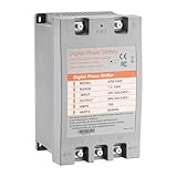
- [ Easy Installation ] Simply wire single-phase input (L/N) and three-phase motor output (U/V/W). No programming or complex setup required. This single phase to 3 phase converter can plug-and-play.
- [ Safety & Efficiency ] Flame-retardant housing and automatic restart protect motors from overloads. Reduces high-frequency noise and lowers long-term grid costs. This 3 phase inverter technology ensures stable 220-240V output.
- [ Wide Compatibility ] Powers 10HP motors for air compressors, pumps, grinders, saws, and fans. Perfect for residential and light commercial use. The 3 phase converter supports diverse equipment needs.
- [ Compact & Lightweight ] Space-saving design ( size: 9.8x6x5.3 inch, weight: 5.2 lbs) suits tight workshops. Durable yet portable, ideal for garages or small workspaces. The digital phase shifter maximizes efficiency.
- [ Critical Guidelines ] Always pair with an air switch on the power side (not motor side). Use one 3 phase converter per motor. Verify wire specification and motor power for optimal performance.
- Phase current using two or three shunts, Hall sensors or isolated current sensors.
- DC-link current or voltage.
- Power-device or heatsink temperature.
- Ground fault or insulation fault conditions where applicable.
- Rotor position from Hall sensors, an encoder or sensorless estimation.
Protection should include hardware shutdown independent of firmware where practical. Relevant functions include DC-bus overvoltage and undervoltage, phase or DC-link overcurrent, short-circuit response, driver undervoltage lockout, overtemperature and emergency disable. High-power reference designs such as TI’s TIDA-01540 combine isolated gate driving with programmable dead-time and multiple hardware protection functions.
Current sensing and PWM cannot be designed separately. At very low or high duty cycles, high modulation index or high switching frequency, switching transitions may leave too little quiet time for accurate ADC sampling. The selected modulation method must provide usable sampling windows for the chosen shunt arrangement.
Recommended design process
- Define the application. Establish DC-input range, motor voltage, continuous and peak current, electrical frequency, switching frequency, regenerative operation, isolation requirements and cooling method.
- Select the topology. Use the conventional six-switch, two-level bridge unless a three-level, four-switch, matrix or other topology has a specific advantage.
- Select the devices. Match voltage, current, switching loss, reverse recovery, short-circuit capability and thermal limits to the worst operating point.
- Select the gate-driver architecture. Decide between integrated three-phase driving, three half-bridge drivers, six isolated channels, bootstrap supplies and isolated high-side supplies.
- Implement PWM interlock. Configure complementary outputs, hardware dead-time, safe all-off startup and a hardware fault-disable path.
- Design sensing and protection. Place sensors so that faults are detected quickly and measurement returns do not share noisy power-current paths.
- Lay out the power stage. Minimise switching loops, keep gate loops short, use appropriate isolation spacing and place bypass capacitors directly at the bridge.
- Test at low energy. Use a low-voltage, current-limited supply. Test gate signals without the motor, verify actual gate-to-source or gate-to-emitter waveforms, confirm dead-time and exercise the fault input.
- Increase energy gradually. Check switching-node overshoot, ringing, driver supply droop, cross-conduction current and thermal behaviour before applying full bus voltage or load.
Gate resistance, dead-time, switching frequency, DC-link capacitance, snubber values, current-sense gain and heatsink size are application-specific. They cannot be safely copied as universal numbers from another diagram.
PCB layout essentials
- Keep the high-current DC-link and commutation loops short and wide.
- Place local film or ceramic bypass capacitors close to the bridge devices.
- Keep each gate loop short and minimise common-source or common-emitter inductance.
- Use Kelvin source or emitter connections for gate-driver returns where available.
- Separate noisy power returns from sensitive current-sense and controller returns, while following the driver manufacturer’s grounding scheme.
- Control dv/dt and di/dt rather than assuming the schematic determines all switching behaviour.
- Maintain creepage and clearance for the maximum working voltage, transient environment and required insulation.
- Provide a defined mechanical path for heat from devices to the heatsink or cold plate.
Common failure modes
Shoot-through
Likely causes include insufficient dead-time, driver interlock failure, incorrect PWM polarity, gate ringing, Miller-induced false turn-on or unsafe reset behaviour. Use hardware interlock, gate pull-downs, suitable driver UVLO, short gate loops and an independent shutdown path.
False turn-on
Fast switching-node transitions can couple through Miller capacitance into an off gate. Strong turn-off drive, Miller clamps, suitable negative bias, Kelvin returns, controlled gate resistance and an adequate driver CMTI rating can reduce the risk.
Bootstrap collapse
Check whether the high-side device stays on too long, whether the low-side interval refreshes the bootstrap capacitor, and whether the diode, capacitor and driver supply are correctly rated. Startup sequencing and stopped-rotor conditions can expose problems that do not appear during normal rotation.
Excessive ringing
Ringing usually indicates excessive parasitic inductance, overly fast gate drive or inadequate local decoupling. Measure the switching node with a properly rated differential probe before selecting a snubber or changing gate resistance.
Do these 3 things before closing this tab:
1Scan for outdated or missing drivers - takes under a minute2Clear out junk files and repair common Windows errors3Fix the driver behind crashes, sound loss and screen glitchesOvercurrent at startup
Check phase order, Hall or encoder polarity, rotor alignment, PWM polarity, current-sensor offset, duty-cycle initialisation and the motor’s mechanical load. Begin with a low bus voltage and conservative current limits.
Best Value

- Easy To Wire: The frequency converter is easy to use and wire. It would be more convenient to connect to wires with screw terminals.
- Multi : This variable frequency inverter has multi such as over current, over voltage and under voltage, module failure, over heat, short circuit, etc, and provide low electromagnetic interference.
- Applications: The frequency inverter has single‑phase input and 3‑phase output, and is suitable for 3‑phase motors with a voltage of 220V. It is used to control the start, stop, speed adjustment and forward and reverse rotation of the motor.
- Applications: The frequency inverter has single‑phase input and 3‑phase output, and is suitable for 3‑phase motors with a voltage of 220V. It is used to control the start, stop, speed adjustment and forward and reverse rotation of the motor.
- Variable Frequency Drive: The inverter is a device used to adjust the speed of the motor, it has high torsion and wide speed regulation. The speed governor is equipped with a digital display, with clear readings and convenient parameter setting.
Dead-time distortion
Excessive dead-time can cause current distortion, torque ripple, audible noise and low-speed control error. Reduce it only after confirming that the actual devices are fully off before their complements turn on.
Alternatives to the standard bridge
A three-level inverter can reduce device voltage stress and waveform distortion but requires more switches, drivers and balancing control. A four-switch three-phase inverter reduces hardware count but has unequal phase-leg behaviour and more restrictive modulation. A matrix converter avoids a conventional DC link but uses bidirectional switches and complex commutation. An integrated smart power module can simplify layout and protection, although package thermal limits, vendor dependence and replacement availability must be considered.
Reduced-switch research topologies are not drop-in replacements for the conventional six-switch bridge. Their voltage utilisation, current paths, sensing, control and fault behaviour must be analysed independently; one example is described in this research paper.
Evaluation boards and reference designs
Reference hardware is useful for understanding a circuit diagram, but it is not automatically a safe or production-ready design for another voltage, motor, enclosure or cooling system.
| Development need | Relevant example |
|---|---|
| Industrial high-voltage inverter architecture | TI TIDA-01540, a documented isolated-gate-driver reference design for high-power inverter development. |
| Compact integrated motor controller with three-shunt sensing | ST EVSPIN32F0601S3, using an integrated 600-V three-phase gate driver and MCU. |
| Single-shunt motor-control evaluation | ST EVSPIN32F06Q1S1, supporting FOC and six-step control. |
| FPGA-based PWM generation | Microchip three-phase PWM IP, with complementary outputs, dead-time and shutdown control. |
| External MCU with consolidated gate-drive functions | Infineon MOTIX 6EDL7141, supporting three-PWM and six-PWM interfaces. |
Choose hardware by voltage, current, motor type, sensing method, isolation, cooling and control requirements—not by the number of switches shown in a marketing diagram.
Safety before testing
The controller may operate at 3.3 V or 5 V while the DC bus remains lethal. DC-link capacitors can retain dangerous energy after power is removed. Use suitable fusing, precharge, discharge, enclosure, isolation, interlocks and qualified personnel.
Never connect the ground clip of a conventional earth-referenced oscilloscope probe to a floating high-side switching node. Use a correctly rated differential probe or isolated measurement system and observe its common-mode, bandwidth, insulation and creepage limits. Apply the safety and compliance requirements appropriate to the equipment category, voltage, power, installation and jurisdiction.
Quick wins for a faster PC:
Repair Windows errors before they cause bigger problemsFix Now →Fix the driver behind crashes, sound loss and screen glitchesFind Drivers →Quick Recap
Product prices and availability are accurate as of the date/time indicated and are subject to change. Any price and availability information displayed on Amazon at the time of purchase will apply.


Leave a Reply