Free tools Windows power users keep installed
One-click scans. No signup required.
Some links on this page are affiliate links: if you buy through them we may earn a commission, at no extra cost to you.
For a small, low-current circuit, the simplest true bipolar supply is two equal batteries in series with their junction used as 0 V. Two nominal 9 V batteries provide approximately +9 V, 0 V and −9 V. If you only have one DC supply, a resistor divider can create a midpoint—but that is a virtual ground, not a robust negative power rail.
Choose the solution by asking three questions: what voltage must each rail provide, how much current will each rail draw, and must the outputs be isolated or independently regulated?
What “bipolar” or “split-rail” power means
A bipolar, dual-rail or split supply provides two voltages relative to a shared reference:
+12 V   positive rail
  |
  |      24 V rail-to-rail
  |
  0 V    circuit reference
  |
  |
−12 V   negative rail
The 0 V node is a voltage reference. It is not automatically earth, protective earth, chassis ground or the negative terminal of an external adapter.
#1 Best Overall

- Adjustable positive / negative supplies: ±5 to ±15Vdc, 175mA to 750mA per supply
- LED on indicator
- 120Vac input
- 48-Piece kit
- PC board construction
- True dual rails: positive and negative outputs are generated as supply rails and can generally source current independently.
- Virtual ground: a midpoint made from a resistor divider, buffer or rail-splitter circuit. It may be suitable as a signal reference but can move under load.
- Floating supply: an electrically isolated supply whose reference can be assigned to the circuit ground.
This distinction matters. Calling the midpoint of a lightly loaded divider “−9 V” does not make it equivalent to a regulated −9 V output.
Choose the circuit before building
| Requirement | Best starting point | Important limitation |
|---|---|---|
| Fast experiment, very low current | Two batteries in series | Voltage falls with discharge and the rails are not regulated |
| Signal reference only | Resistor divider | Midpoint moves when the load is unbalanced |
| Low-current but stiffer midpoint | Buffered divider or rail splitter | Buffer current, stability and heat limits still apply |
| Adjustable regulated rails | LM317 plus LM337 | Needs suitable raw voltage, filtering and thermal design |
| Fixed ±5 V from a 3.3–5 V source | Split-rail charge-pump converter | Voltage and current are device-specific |
| True isolation or substantial current | Isolated DC/DC module or transformer supply | More expensive and may require filtering or post-regulation |
Do not assume that a 12 V adapter can become ±12 V by adding a midpoint. A passive midpoint produces approximately +6 V and −6 V. To obtain ±12 V from a single 12 V input, you need a boost/inverting or isolated conversion topology.
Build 1: two 9 V batteries
This is the best answer when “simplest” means the fewest parts and the quickest working result.
Windows Errors? Fix Them Before They Spread
Repair common Windows errors and clear accumulated junk for a smoother, more stable PC - no reinstall needed.Free scan · no reinstallCrashes, No Sound, or Screen Glitches?
Random freezes, missing sound and display glitches usually trace back to one bad driver. Find and replace yours safely.Free scan · under a minute +9 V
|
Battery 1
|
0 V -----+----- midpoint
|
Battery 2
|
−9 VParts
- Two equal 9 V batteries, preferably the same chemistry and age.
- Two battery connectors or holders.
- Three labelled wires or a three-pin connector.
- Optional switch and local decoupling capacitors.
Connections
- Connect the positive terminal of Battery 1 to the circuit’s +9 V output.
- Connect the negative terminal of Battery 1 to the positive terminal of Battery 2.
- Use that junction as 0 V.
- Connect the negative terminal of Battery 2 to the circuit’s −9 V output.
Because the battery stack is floating, you may assign its midpoint as the circuit reference. With fresh nominal 9 V batteries, a meter should read approximately +9 V from the midpoint to the upper terminal, −9 V from the midpoint to the lower terminal, and approximately 18 V from the positive rail to the negative rail.
Limitations
- A “9 V” battery is nominal; its voltage varies with chemistry, state of charge, load and internal resistance.
- The two batteries may discharge at different rates, so the rails will not remain perfectly symmetrical.
- Current capability and runtime are limited.
- Rechargeable and non-rechargeable batteries should not be mixed casually.
- Connecting an external grounded device to one terminal can bypass part of the battery stack.
Before connecting an oscilloscope, USB device or another supply, determine whether its ground is already connected to earth or to another circuit. A floating battery supply is forgiving; an accidental connection can still short one battery or defeat the intended midpoint.
Build 2: a resistor-divider virtual ground
A single DC supply can be divided into two nominal halves:
+9 V ── 10 kΩ ──+── 10 kΩ ── 0 V input
                 |
             virtual 0 V
With a 9 V input, the midpoint is approximately 4.5 V. If the midpoint is renamed 0 V, the apparent rails are approximately +4.5 V and −4.5 V. This does not produce ±9 V.
Rank #2
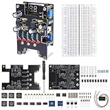
- 【All-in-One Breadboard Power Solution】This DIY power supply module integrates multiple commonly used voltage outputs into a single board, eliminating the need for separate regulators and repeated rewiring. It provides a cleaner, safer, and more efficient way to power breadboard experiments and electronics projects.
- 【Designed for Practical Electronics Projects】Well-suited for powering microcontrollers, sensors, and small electronic circuits. Ideal for electronics labs, workshops, makerspaces, and users who frequently work with breadboards and need stable, organized power distribution.
- 【Reduce Wiring Errors and Setup Time】By centralizing power outputs, this module helps minimize wiring mistakes that can damage components or interrupt experiments. Spend less time building power circuits and more time testing and learning.
- 【Adjustable Output with Visual Voltage Display】The adjustable output features a built-in digital display, allowing you to fine-tune voltage levels and visually confirm settings before connecting your circuit. Improves confidence and reduces trial-and-error during setup.
- 【Flexible for Advanced Applications】In addition to standard outputs, the module includes optional negative voltage support for users working with analog circuits or advanced electronics experiments, without complicating everyday use.
The divider current in this example is:
I = 9 V / (10 kΩ + 10 kΩ)
I = 0.45 mA
A load current comparable with 0.45 mA can move the midpoint substantially. A circuit drawing 10 mA from one side is already demanding far more current than the divider continuously provides.
TI describes the resistor divider as the simplest rail-splitting method, while noting that it becomes unbalanced under load: TI’s split-rail overview.
Good uses
- Biasing an op-amp input.
- Creating a signal reference for a low-current sensor circuit.
- Very low-current analog experiments.
- Circuits whose current is deliberately centred around the midpoint.
Bad uses
- Headphones, speakers or other audio power loads.
- Motors, relays, LEDs or several independent circuits.
- Large or rapidly changing current on only one rail.
- Any design that requires an independently regulated negative supply.
Lower resistor values make the midpoint somewhat stiffer but waste more current. They do not transform the divider into an isolated, independently regulated supply.
Build 3: a buffered virtual ground
A buffered rail splitter uses a divider to establish half the input voltage, then an op-amp or dedicated buffer to hold that midpoint near the desired reference. This is much better than a bare divider for modest signal currents, and it is a common approach in single-supply analog circuits.
Quick wins for a faster PC:
Clear out junk files and repair common Windows errorsFree Scan →Scan for outdated or missing drivers - takes under a minuteDriver Scan →Repair Windows errors before they cause bigger problemsFix Now →The buffer must be able to source and sink the expected midpoint current. Check its output-current rating, output-voltage range, common-mode range, power dissipation and stability with the intended capacitors. A buffer that can source current may not be equally good at sinking it.
A buffered virtual ground is still not a second isolated supply. It shares the input’s electrical reference and can fail or overheat if an external device forces current into the midpoint. Analog Devices explains the rail-splitter concept and feedback-buffer approach in its virtual-ground article.
Build 4: a regulated LM317/LM337 dual supply
For adjustable, ground-referenced rails with more current capability than a divider, use a genuinely split source followed by separate regulators:
Rank #3

- Adjustable DC Regulated Power Supply DIY Kit
- Input Voltage: 24V AC
- Input Current: Max 3A
- Output Voltage: 0-30V (continuously adjustable)
- Output Current: 2mA-3A (continuously adjustable)
isolated centre-tapped AC or split DC source
                    ↓
              rectifier and filter
               ↙             ↘
          LM317 (+ rail)  LM337 (− rail)
               ↓             ↓
              +V             −V
                    midpoint 0 V
The source may be an isolated centre-tapped transformer secondary, a suitable split DC source or another correctly designed isolated supply. A beginner-friendly construction should use an enclosed, certified low-voltage source rather than exposed mains wiring.
The Tool Desk
Outbyte PC Repair FREEClear out junk files and repair common Windows errorsFree Scan →Outbyte Driver Updater FREEScan for outdated or missing drivers - takes under a minuteDriver Scan →The LM317 is an adjustable positive regulator with a catalog rating up to 1.5 A and an adjustment range of approximately 1.25 V to 37 V, subject to input voltage, dropout, thermal, package and operating-condition limits. The LM317/LM337 evaluation design shows the corresponding positive and negative regulator architecture.
Setting the output voltage
For an LM317-style regulator:
VOUT ≈ 1.25 V × (1 + R2/R1) + IADJ × R2For a first approximation using the common 240 Ω programming resistor:
R2 ≈ R1 × (VOUT / 1.25 − 1)For approximately 12 V:
R2 ≈ 240 Ω × (12 / 1.25 − 1)
R2 ≈ 2.06 kΩ
A 2.0 kΩ resistor gives approximately 11.7 V before adjustment-current and resistor-tolerance effects. Use fixed precision resistors where possible, or a multiturn trimmer with a safe maximum setting. The LM337 uses the same relationship in magnitude, but its resistor connections and pinout must follow the exact LM337 datasheet and package drawing. Never substitute an LM317 pinout diagram for an LM337 without checking the device.
Input headroom and ripple
A linear regulator needs its input to remain above the output by its dropout requirement plus a margin for ripple. TI gives approximately 2 V as a typical LM317 dropout figure, but the actual value depends on load, temperature and device version.
Recommended Free Tools
With a capacitor-input rectifier, estimate full-wave ripple as:
ΔV ≈ ILOAD / (fRIPPLE × C)On 60 Hz mains, full-wave ripple is 120 Hz. For 100 mA and 2200 µF:
Rank #4

- Chanzon Power Transistors Assortment Kit for General Purpose
- Model: (Each 20pcs) 2N7000 2N2222A 2N2907A 2N3904 2N3906 2N5551 2N5401 S8050 S8550 A1015 C1815 A42 A92 A733 C945 S9014 BC327B BC337B BC547B BC557B
- Type: NPN & PNP Power BJT Bipolar Junction Transistor and 2N7000 MOSFET for Versatile Applications
- Application: Ideal for Power Supplies, Signal Processing, and Amplification in Diverse Electronic Circuits
- Package: Organized in a Durable Plastic Box with Separate Compartments for Each Part
ΔV ≈ 0.10 / (120 × 0.0022)
ΔV ≈ 0.38 V
The unregulated waveform must remain above the regulator’s required input at the ripple valley. Also allow for transformer regulation, diode drops, mains variation, capacitor tolerance, startup behaviour and the worst-case condition of the negative rail.
Heat calculation
Estimate each regulator separately:
P ≈ (VIN − VOUT) × ILOADFor 18 V into a 12 V regulator at 250 mA:
P ≈ (18 − 12) × 0.25
P ≈ 1.5 W
That is enough to require attention to package temperature and possibly a heatsink. The positive and negative regulators may dissipate different amounts if the rail currents or raw input voltages differ. Internal current limiting and thermal overload protection, listed for the LM317 by TI, do not make continuous overheating safe.
Capacitors and protection
- Use reservoir electrolytics after rectification, with adequate voltage ratings and correct polarity.
- Place 100 nF ceramic bypass capacitors close to regulator input and output pins where the datasheet recommends them.
- Use output capacitors only as permitted by the regulator datasheet and selected for stability.
- Add bleeder resistors across large reservoir capacitors so stored voltage falls after shutdown.
- Use reverse-protection diodes around the regulators where required by the datasheet.
- Fuse the input and use a correctly rated switch.
- Provide an enclosure, strain relief and ventilation appropriate to the source and heat.
Mains-powered transformer construction involves hazardous voltages and requires suitable insulation, fusing, earthing where applicable and safe enclosure practices. For a beginner project, use an isolated low-voltage adapter or a preassembled isolated transformer module instead of working with exposed mains wiring.
Independent reader supportYour contribution helps us test, update, and keep practical guides available for everyone.Modern converter alternatives
A converter is often a better choice than linear regulators when the input is a battery or when heat must be minimized.
Fixed ±5 V converters
TI’s TPS65133 is specified for ±5 V outputs up to 250 mA per output from a 2.9 V to 5 V input. TI also gives typical efficiency above 90% under stated conditions; this is not a universal efficiency guarantee. It is a surface-mount switching solution, so layout and filtering matter.
The LM27762 provides adjustable positive and negative outputs of approximately ±1.5 V to ±5 V, with up to ±250 mA from a 2.7 V to 5.5 V input. Its low-noise LDO regulation can be useful for analog circuits, but the voltage range does not directly cover ±9 V or ±12 V and its compact package is less convenient for beginners.
Do these 3 things before closing this tab:
1Scan for outdated or missing drivers - takes under a minute2Repair Windows errors before they cause bigger problems3Fix the driver behind crashes, sound loss and screen glitchesThe TC1044S can invert or double a supply, but it is not a complete universal dual-rail supply. Follow its datasheet for output current, switching frequency, capacitors and voltage limits.
Best Value
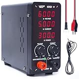
- This variable power supply provides accurate numerical voltage reading up to 00.01V (Every 10mV), current reading up to 0.001A (Every 1mA), power reading up to every 0.1W. Comes standard with automatic Constant Voltage, Constant Current function. Please read the product manual carefully and ensure you fully understand the specifications of the equipment to be connected before use
- You can easily adjust the lab power supply's output to the precise parameters you need, no more fiddlign with corase and fine adjustment dials. This bench power supply's adjustment dials are made from digital rotary encoders, this gives greater lifespan even when used frequently. Plus, you don't need to short-circuit the terminals to set the adjustable power supply's parameters
- This dc power supply comes with short-circuit protection, active temperature management, overload protection (CC/CV mode), The power supply cuts power, play a warning beep, and shows code "ScP" when a short circuit is detected. The cooling fan activates automatically to maintain optimal operation temperature, and the adjustable power supply cuts power and enters protection mode once overheat is detected
- This compact dc power supply is similar to the size of a lunch box, saving precious work space. The power supply has a maximum power of 300W supporting maximum output of 60V 5A. It has a strong power capacity, and its voltage drop is low when powering a load
- This WEP dc power supply variable is covered by our exclusive 1-year USA technical support, with 24-hour assistance from our dedicated team. Note: This product is rated for 110-127V USA specifications. Do not connect this iron to a 220V power socket
Isolated ±12 V modules
When a single DC input must produce genuinely isolated dual rails, an isolated module is often simpler than designing an inverter. The TRACO TEL 15-2422WIN listing specifies isolated +12 V and −12 V outputs at 625 mA per output from a 9 V to 36 V input. Depending on the application, it may still need filtering, post-regulation or thermal management.
Always verify isolation rating, output regulation, permissible unbalanced loading, ripple, input range and continuous thermal performance. Do not rely on a marketplace module labelled “±12 V” unless its schematic or datasheet confirms how the negative output is produced.
Testing procedure
- Leave the project load disconnected.
- Check regulator orientation and the exact package pinouts.
- With power off, measure resistance between each rail and 0 V to look for an obvious short.
- Power through a current-limited bench supply or protective fuse.
- Measure the positive rail from red meter lead to 0 V.
- Measure the negative rail with the black lead on 0 V and red lead on the negative rail.
- Measure positive rail to negative rail.
- Apply a dummy load to each rail separately.
- Observe midpoint movement, ripple and regulator temperature.
- Connect the intended circuit only after the unloaded and dummy-load tests pass.
For a nominal ±12 V supply, expected readings are approximately +12 V from positive rail to ground, −12 V from negative rail to ground and 24 V from positive rail to negative rail. If the negative rail appears positive, check the meter lead orientation before changing the wiring.
Troubleshooting by symptom
The rails are correct with no load but collapse under load
A divider or virtual-ground buffer may be overloaded. Other causes include regulator dropout, inadequate reservoir capacitance, excessive ripple, insufficient transformer voltage, an incorrect regulator connection or a shorted load.
The midpoint is not exactly zero
This is normal for a passive divider, unequal battery pair or independently adjusted regulators. Measure both rails relative to the midpoint under the actual load rather than assuming symmetry.
One regulator is much hotter
Calculate dissipation independently. The rail currents may differ, or one regulator may receive a higher raw input voltage. Check heatsink contact, airflow and the regulator’s safe operating limits.
Connecting USB causes a short or instability
The USB device may already connect its ground to the computer or charger. That external ground can short or overload a virtual midpoint. Use an isolated supply when the circuit reference must remain separate.
There is excessive ripple or switching noise
Check reservoir capacitance, capacitor ESR and polarity, rectifier wiring, grounding and regulator headroom. Switching converters also require the manufacturer’s recommended layout, inductors or capacitors, short current loops and suitable filtering.
Capacitors heat, leak or fail
Immediately remove power and check electrolytic polarity, voltage ratings, rectifier orientation, centre-tap wiring and possible reverse-voltage conditions. Large capacitors can retain dangerous energy after shutdown; verify discharge with a meter.
Final selection checklist
- Do you need ±9 V, ±12 V, ±5 V or only a midpoint reference?
- Have you calculated positive-rail, negative-rail, peak and transient current?
- Are the rail currents balanced, or does one rail carry most of the load?
- Is a virtual ground acceptable, or do you need true independently usable rails?
- Must the output be isolated from USB, an oscilloscope or another supply?
- For linear regulators, does the ripple valley stay above the required headroom?
- Have you calculated heat for each regulator?
- Are capacitor voltage ratings, polarity, fusing and discharge handled correctly?
- Have you tested both rails relative to 0 V and relative to each other?
For a quick, low-current experiment, use two batteries and their junction as 0 V. For signal biasing from one supply, use a divider or buffered midpoint. For a dependable adjustable supply, use a properly designed LM317/LM337 circuit. For isolation, efficiency or substantial unbalanced current, use an appropriately rated isolated or switching converter.
Quick Recap
Product prices and availability are accurate as of the date/time indicated and are subject to change. Any price and availability information displayed on Amazon at the time of purchase will apply.
What’s actually slowing this PC down?
Pick the symptom - the matching free tool is one click away.


Leave a Reply